


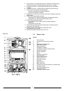
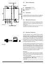
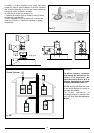
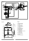
VIEW OF THE BOILER CONNECTIONS
LEGEND:
A = Central Heating Flow
C = Gas Inlet
E = Central Heating Return
F = Safety Valve
G = Pump transportation screw
(remove before igniting the boiler)
H = Automatic By-pass pipe
CENTRAL HEATING
Detailed recommendations are given in BS 6798:1987 and BS 5449-1:1990,
the following notes are given for general guidance.
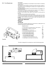
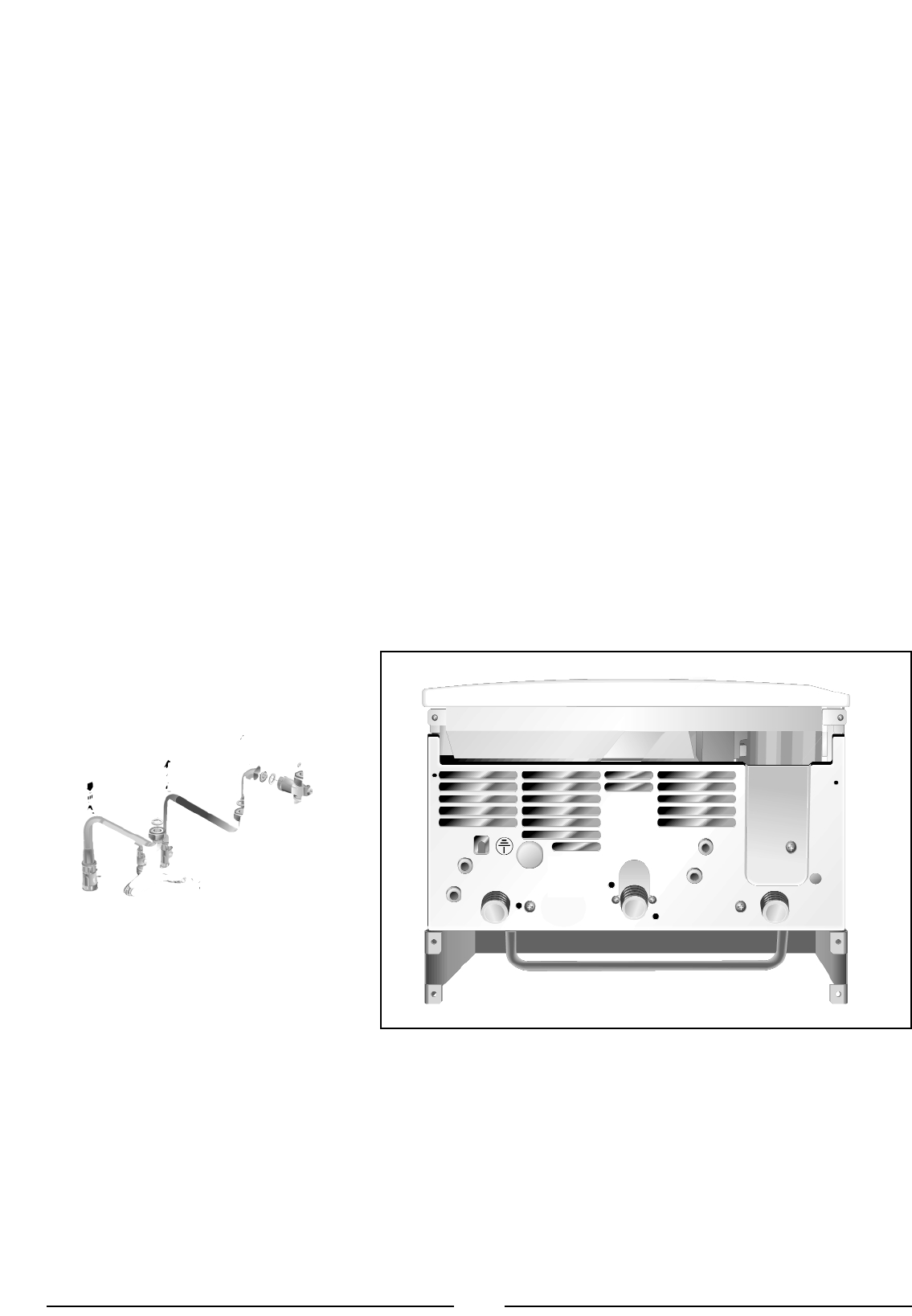
2.8 WATER CONNECTIONS
2.7 GAS CONNECTION
The local gas region contractor connects the gas meter to the service pipe.
If the gas supply for the boiler serves other appliances ensure that an
adequate supply is available both to the boiler and the other appliances
when they are in use at the same time.
Pipe work must be of an adequate size. Pipes of a smaller size than the
boiler inlet connection should not be used.
7
marked “L”.
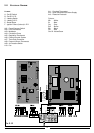
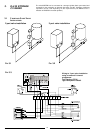
Note: The diagrams for the electrical system are indicated in section 2.12.
Warning, this appliance must be earthed.
External wiring to the appliance must be carried out by a competent person
and be in accordance with the current I.E.E. Regulations and applicable
local regulations. The microSYSTEM range of boilers are supplied for
connection to a 230 V
~
50 Hz supply.
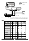
The supply must be fused at 3 A.
The method of connection to the electricity supply must facilitate complete
electrical isolation of the appliance, by the use of a fused double pole
isolator having a contact separation of at least 3 mm in all poles or
alternatively, by means of a 3 A fused three pin plug and unswitched
shuttered socket outlet both complying with BS 1363.
The point of connection to the Electricity supply must be readily accessible
and adjacent to the appliance unless the appliance is installed in a bathroom
when this must be sited outside the bathroom (see section 2.2).
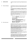
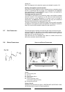
FIG. 2.3
F
IG. 2.4
F
A
D
B
C
E
SC004A