


19
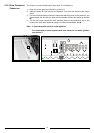
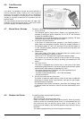
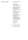
The flue connector has two apertures, readings can be
taken for the temperature of the combustion by-products
and of the combustion air, as well as of the concentrations
of O
2
and CO
2
, etc. .
To access these intakes it is necessary to unscrew the front
screw and remove the metal plate with sealing gasket.
To achieve the best test conditions, turn the central heating
adjustment knob “G” to the “max” position and remove the
electrical connection to the heating sensor (see section 6.).
This will allow the appliance to operate at the maximum
heating power.
4.5 COMBUSTION ANALYSIS
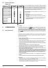
4.4 INITIAL START-UP
THE CHECKS TO BE RUN BEFORE INITIAL START-UP ARE AS FOLLOWS:
1. Make sure that:
-the screw on the automatic air valve has been loosened when the
system is full;
- If the water pressure in the system is below 1.5 bar, bring it up to the
appropriate level;
-Ensure that the gas cock is closed;
-Make sure that the electrical connection has been made properly and
that the earth wire is connected to an efficient earthing system;
-Supply power to the boiler by pushing the On/Off button “A” (see
F
IG.4.1) - the L.E.D. “B” will illuminate. Then push the button “C” in for
central heating - the L.E.D. “D” will illuminate. This will start the
circulation pump. After 7 seconds, the boiler will signal a shutdown due
to ignition failure. Leave the boiler as it is until all of the air has been bled
from the system.
-Loosen the cap on the head of the pump to eliminate any air pockets;
-Repeat the procedure for bleeding the radiators of air;
-Check the system pressure and, if it has dropped, open the filling loop
again to bring the pressure back up to 1.5 bar.
2. Make sure that all gate valves are open;
3. Turn on the gas cock and check the seals on the connections with an
approved soap solution and eliminate any leaks.
4. Press the reset button “E” for the lighting system; the spark will light the
main burner. If the burner does not light the first time, repeat the
procedure.
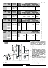
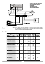
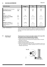
5. Check the minimum and maximum pressure values for the gas going to
the burner; adjust it if needed using the values indicated in the table in
section 5 (See the relative section for burner pressure adjustment within
the servicing manual).
B
4
5
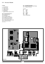
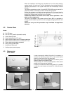
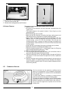
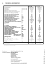
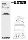
To dismantle the front casing panel it is necessary to:
1 - Remove the two screws “B”;
2 - Move the front casing panel up and lift forward.
FIG. 4.2