


17
MTS (GB) Limited support the initiative. Within the information pack
you will find a copy of the logbook. It is important that this is
completed in the presence of your customer, they are shown how to use it,
and it is signed by them. Please instruct your customer that they must have
their logbook with them whenever they contact a service engineer
or us.
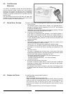
Preliminary electrical system checks to ensure electrical safety must be
carried out by a competent person i.e. polarity, earth continuity, resistance to
earth and short circuit.
F
ILLING THE HEATING SYSTEM:
Remove the panels of the case and lower the control panel (see section
3.3 for further information).
Open the central heating flow and return cocks supplied with the
connection kit (there are two isolation points on the return connection).
Unscrew the cap on the automatic air release valve one full turn and leave
open permanently.
Close all air release valves on the central heating system.
Gradually open valve(s) at the filling point (filling-loop) connection to the
central heating system until water is heard to flow, do not open fully.
Open each air release tap starting with the lowest point and close it only
when clear water, free of air, is visible.
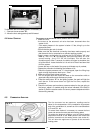
Purge the air from the pump by unscrewing anticlockwise and
removing the pump plug and also manually rotate the pump shaft in
the direction indicated by the pump label to ensure the pump is free.
Refit the pump plug.
Continue filling the system until at least 1.5 bar registers on the pressure
gauge.
Inspect the system for water leaks and remedy any leaks discovered.
G
AS SUPPLY:
Inspect the entire installation including the gas meter, test for soundness
and purge the supply as described in BS 6891:1988.
Open the gas cock (supplied with the connection kit) to the appliance and
check the gas connections on the appliance for leaks.
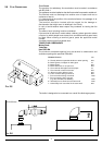
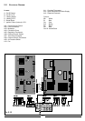
4. COMMISSIONING
4.1 INITIAL PREPARATION
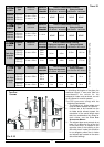
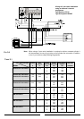
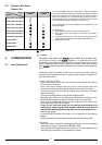
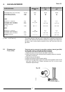
Boiler microSYSTEM microSYSTEM
21 RFFI 28 RFFI
Cylinder
= Ideal
= Possible
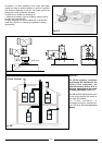
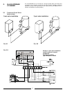
The microSYSTEM is able to be connected to a specially designed
kit for the management of D.H.W. production. This kit gives priority to
production of D.H.W. unlike traditional systems where the boiler
power is split between C.H. and D.H.W. This generally enables a
smaller storage cylinder to be chosen as the boiler’s full output will be
channelled into the cylinder allowing for a quick heat-up.
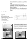
The kit (ARISTON part number
706329) can be obtained from an
ARISTON supplier.
The kit consits of:
1) Electronic module able to plug into the boiler’s P.C.B;
2) 3-way priority valve with actuator for connection to the boiler’s
flow outlet;
3) A limit thermostat (80˚C) to check the water temperature of the
heating flow to the cylinder, to be installed within the boiler;
4) Pipes and accessories.
Contract STI 125 Indirect
Comfort STI 125 Indirect
Contract STI 150 Indirect
Comfort STI 150 Indirect
Contract STI 210 Indirect
Comfort STI 210 Indirect
Contract STI 300 Indirect
SB 125 Indirect
SB 150 Indirect
SB 200 Indirect
TABLE
3.2
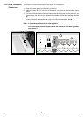
3.2 DOMESTIC HOT WATER
PRIORITY KIT