


11 - 43
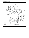
11.14 ELECTRICAL FOR SERIAL
NUMBERS ABOVE 5,000 AND BELOW
9,999
Safety Interlock System
WARNING: Safety Interlock failure and improper
operation of unit can result in death or serious injury.
Check system before each use to make sure it is
functioning properly.
Perform the following tests to ensure the safety
interlock system is working properly. If the unit does not
perform as stated contact your Ariens dealer for
repairs.
Initial check out: Make sure that all switches are in their
proper position for starting: (A) PTO off. (B) transaxle in
neutral position. (C) operator on the seat. If there is no
battery voltage to start the engine, use the following
steps to determine the problem.
STEP 1
Check out the battery. Use a voltmeter to check for
proper voltage. Replace the battery if necessary and/or
charge to proper level. Refer to Battery.
STEP 2
Use a voltmeter to make sure you have battery voltage
to terminal B on the back side of the ignition switch in
the off position. If you don’t have battery voltage to
terminal B check the battery connection and the fuse in
the red lead.
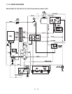
STEP 3
With the ignition switch in the "run" position, check to
see if the battery voltage is being transferred from
terminal B to terminal L. Terminal L on the ignition
switch supplies battery voltage to the back of the PTO
switch on the purple lead and on to the neutral
switches on the red/green lead. Terminal A also
supplies battery voltage to the hour meter.
For models with serial numbers between 5,000 and
9,999 with the key switch in the "run" position, the seat
switch "on" and the parking brake "off" power is
supplied to terminal 86 of the start relay. Terminal 86
will also have power if the key switch is in "run", the
PTO switch is "off" and the steering arms are in the
"neutral" position. The engine will start in either case.
The effect this has on operation is that before the PTO
switch can be turned "on" or the steering arms can be
taken out of neutral it is required that the seat switch is
"on" and the parking brake is "off".
The hour meter will run whenever the key switch is in
the "run" position.
STEP 4
With ignition switch in the "start" position, battery
voltage is transferred from terminal B to S. Terminal S
transfers battery voltage through the PTO switch
(disengaged), the two neutral switches (engaged) and
through the parking brake switch (engaged) to the
starter solenoid.
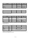
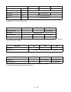
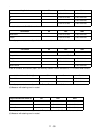
PTO clutch check out: Remove the wiring harness PTO
clutch leads from the clutch. With a multimeter check
the clutch coil for resistance to see if the coil is good.
The clutch used should have a coil resistance
according to the table below. If the coil is bad there will
be no resistance or it will be higher.
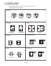
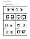
Ignition switch check out: Battery voltage check in the
"off" position, check for voltage at terminal B. It should
not be present on terminals A, S, L.
With the ignition switch in the "run/light" position, check
for battery voltage at terminal B, A, L, Y. It should not
be present at terminal S.
With the ignition switch in the "run" position, check for
battery voltage at terminals B and L.
With the ignition switch in the "start" position, check for
battery voltage at terminals B, S, L.
PTO switch check out: The PTO switch is a push/pull
switch with normal open and closed contacts. Power
transfer should be checked with a voltmeter. The
switch contacts should be checked with an ohm meter
with the wire harness plug removed. The light switch is
similar to the PTO switch with only one set of contacts.
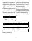
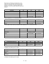
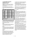
Test Steering
Levers
PTO Parking
Brake
Engine
1 Neutral
Position
Off Engaged Starts
2 Neutral
Position
On Engaged Doesn’t
Start
3 Neutral
Position
Off Disengaged Doesn’t
Start
4*+ Out of Neutral
Position
Off Disengaged Shuts
Off
5* Neutral
Position
On Engaged Shuts
Off
* Test with engine running.
+ Operator lifts off seat.
Part Number Ohms (± 5%)
00191700 2.84
03643100 3.68
04915400 2.45