


11 - 36
current to a direct current is called a RECTIFIER. A
diode is one type of rectifier.
To check a diode, isolate if from the circuit by
disconnecting one end. With a multitester set on the
lowest ohms scale setting, measure the resistance in
one direction, reverse the test leads, and measure in
the other direction. Readings should be high in one
direction and low in the other. (If the readings are low in
both directions, the diode is shorted, and if the
readings are high, the diode is open.) If the readings
are the same in both directions, the diode is defective
and must be replaced.
IMPORTANT: Diodes are marked to indicate polarity (a
band on one end, an arrow on the side, or they fit on a
holder only one way.
Rectifiers
A battery is charged through the use of an alternator
located in or on the engine. A charging circuit contains
a rectifier because alternators produce alternating
current (AC) and batteries require direct current (DC)
for charging.
The rectifier may be built into the engine or it may be
an external part. It may also contain a regulator to
prevent overcharging the battery. (Servicing of
rectifiers built into the engine should be done by an
approved engine manufacturer’s service center. Such
a service center has access to the information and
parts required to test and repair or replace engine
components, including rectifiers and regulators.)
Units that contain both a rectifier and regulator are
tested in a working circuit to make sure the regulator
portion of the device is operating.
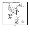
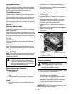
11.9 ELECTRIC CLUTCH
The electric clutch is used to turn on and off the
attachment used on the unit by use of a switch. The
clutch is also designed so that a brake is applied to the
output shaft when the clutch is disengaged (off).
The field coil is mounted to a bearing support and does
not rotate. The rotor is attached to the power output
shaft and rotates around the field assembly. The
armature is attached to the output pulley. The armature
assembly is held close to the rotor by the brake
assembly. The clutch is engaged by applying current to
the coil connection. This results in a current flowing
through the coil, magnetizing the coil pulling the
armature onto the rotor with sufficient force to hold the
two pieces together, effectively connecting the output
and the input shafts together. Pulling the armature
against the rotor pulls it away from the brake, releasing
the brake.
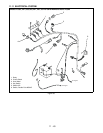
Engine Electrical Components
Engine servicing and repair should be referred to local
engine manufactures service centers that have the
service information and parts available to properly
service the engine. Ariens dealers should be able to
test engines and engine components to pinpoint
troubles and narrow them down to properly advise the
engine serviceman.
IMPORTANT: Check the serial number on the unit. The
serial number will indicate which of the following
sections apply.
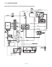
11.10 ELECTRICAL FOR SERIAL
NUMBERS ABOVE 10,000
Safety Interlock System
WARNING: Safety Interlock failure and improper
operation of unit can result in death or serious injury.
Check system before each use to make sure it is
functioning properly.
Perform the following tests to ensure the safety
interlock system is working properly.
Initial check out: Make sure that all switches are in their
proper position for starting: (A) PTO off. (B) transaxle in
neutral position. (C) operator on the seat. If there is no
battery voltage to start the engine, use the following
steps to determine the problem.
STEP 1
Check out the battery. Use a voltmeter to check for
proper voltage. Replace the battery if necessary and/or
charge to proper level. Refer to Battery.
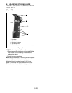
STEP 2
Use a voltmeter to make sure you have battery voltage
to terminal B on the back side of the ignition switch in
the off position. If you don’t have battery voltage to
terminal B check the battery connection and the fuse in
the red lead.
STEP 3
With the ignition switch in the "run" position, check to
see if the battery voltage is being transferred from
terminal B to terminal L. Terminal L on the ignition
switch supplies battery voltage to the back of the PTO
switch on the purple lead and on to the neutral switch
on the red/green lead. Then to terminal 86 on the start
relay.
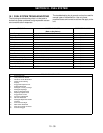
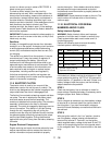
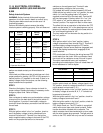
Test Steering Lever PTO Engine
1 Neutral Position Off Starts
2 Neutral Position On Doesn’t Start
4*+ Out of Neutral Position Off Shuts Off
5*+ Neutral Position On Shuts Off
* Test with engine running.
+ Operator lifts off seat.