


11 - 34
IMPORTANT: ALWAYS follow information provided on
battery and battery charger. Contact battery and
battery charger manufacturers for detailed instructions.
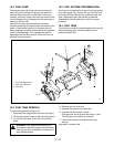
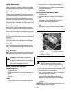
1. Remove battery from unit (see Battery Removal
and Installation).
2. Place battery in a well-ventilated area.
3. Connect positive (+) lead of charger to positive (+)
terminal, and negative (-) lead of charger to
negative (-) terminal.
4. Charge battery according to battery charger and
battery manufacturers’ instructions.
5. Install battery on unit (see Battery Removal and
Installation).
Jump-Starting
Ariens does not recommend jump-starting your unit.
Jump-starting can damage engine and electrical
system components. See your Engine Manual for more
detailed information.
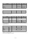
11.4 SWITCHES
Switches either open a circuit to stop current flow or
close and allow current to flow through.
A normally open (N.O.) switch prevents current flow
until the switch is actuated, completing the circuit and
allowing current to flow through it. An example is a light
switch - the lights are off until the switch is actuated
and the lights go on.
A normally closed (N.C.) switch allows current to flow
until the switch is actuated, breaking the circuit and
stopping current flow through it. An example is an
ignition switch that grounds the magneto when in the
off position (completing the circuit) but opens the circuit
when in the ON position allowing the engine to operate.
Switches are selected with regard to Current rating
(contacts must be of sufficient size to carry the required
current), Voltage rating (switches insulated for specific
voltages), Case or housing (switches that are exposed
to moisture and must be sealed to prevent moisture
from entering), and Actuating type (push, pull, rotary,
momentary contact, or micro switches).
NOTE: Check that the connections to the switches are
secure and that a switch is being activated properly
before performing electrical test on switches. (Safety
switches on speed selector and clutch levers may be
out of adjustment and not activating.)
IMPORTANT: When checking switches, remove them
from their respective circuit by disconnecting the wires
from the switch at the connector(s). Damage could
result to the meter or machine components if switches
are left in.
Normally Open Switch
To test a normally open switch (key, headlight, safety,
or seat) connect the ohmmeter across the switch
terminals. Meter should indicate open circuit (infinite
resistance). Activate the switch. The ohmmeter should
read up scale to zero resistance (Close Circuit). This
indicates the switch is operating properly. Also check
from each terminal to the switch case (if case is metal).
Reading should show infinite resistance indicating no
short to ground.
Variation from test results described indicates a
defective switch.
Normally Closed Switch
To test a normally closed switch connect the ohmmeter
across the switch terminals. Meter should indicate a
closed circuit (zero resistance). Activate the switch and
the meter should move to open circuit (infinite
resistance). Check from each terminal to ground
(switch case). Meter should show open circuit (infinite
resistance).
Variation from test results described indicates a
defective switch.
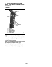
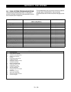
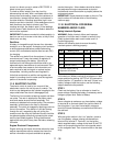
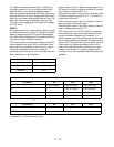
Ignition Switch
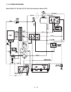
NOTE: Refer to the wiring diagram of the unit involved
to determine switch functions and test using the meth-
ods described.
The ignition switch incorporates a number of functions,
although not all functions are used on all equipment.
The switch has four positions: OFF, RUN with Lights,
RUN, and a momentary contact START position. Use
an ohmmeter to check the continuity of the switch in
each position.