


4 - 14
• Move levers to neutral position.
• Loosen mounting hardware.
• Position steering levers.
• Tighten mounting hardware.
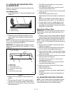
3. Adjust height of steering levers. There is a low and
a high position for steering levers.
• Remove mounting hardware and place
steering levers in the low or high position.
• Tighten mounting hardware.
The forward or backward full travel of the
steering levers is controlled by the position of
the dampener.
4. Locate the dampener. The mounting hole in the
frame should be slotted.
5. Slide adjustment bolt to the back of the machine to
speed the side up (inside of turn). Slide adjustment
bolt forward to slow down this side of the machine
(outside of turn).
6. Adjust as needed. The steering lever neutral
position may need adjustment.
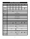
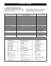
Model IZT 915055, 057, 059, 067, 501 with serial
numbers above 10,000
IMPORTANT: The unit should track within 2 feet
(0.61 m) of a straight line for 30 feet (9.14 m).
The travel of the steering levers may need adjustment
if:
• The unit turns to the right or left when both steering
levers are pushed as far forward as possible.
• The unit turns to the right or left when both steering
levers are pulled back as far rearward as possible.
NOTE: The side the unit turns toward indicates that the
wheel on that side is turning slower than the other
wheel. Either the wheel that is turning faster needs to
slow down or the wheel that is turning slower needs to
be sped up to allow the unit to travel in a straight line.
See steering section for illustrations.
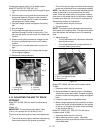
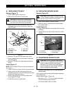
1. Determine which way the unit turns.
2. Tip seat forward
NOTE: The forward travel adjustment bolt adjusts for-
ward travel of the steering lever. The rear travel adjust-
ment bolt adjusts the rearward travel of the steering
lever.
3. Adjust speed by:
• Turning adjustment bolt clockwise to decrease
steering lever travel.
4. Turning adjustment bolt counterclockwise to
increase steering lever travel.
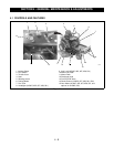
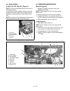
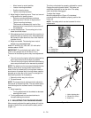
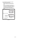
4.11 ADJUSTING THE PARKING BRAKE
When properly adjusted the parking brake will lock the
linkage on both drives and activate the safety switch
(Figure 14).
The drive units should be properly adjusted for neutral.
Engage the parking brake handle. The brake rod
should be positioned to lock the drive. The safety
switch should be disengaged.
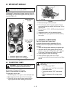
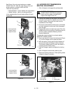
To adjust the linkage:
Move the adjusting nut (Figure 15) clockwise/
counterclockwise as needed to properly position the
brake rod.
NOTE: The safety switch can be loosened for minor
adjustments.
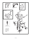
Figure 14
Figure 15
1. Clip
2. Locking Gear
3. Locking Arm
1
2
3
1
1
2
3
3
1. Nylon Adjusting Nut
2. Double Pole Switch
3. Brake Rod
PE0832