


21
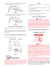
It is recommended that lower water temperatures be used to
avoid the risk of scalding. It is further recommended, in all
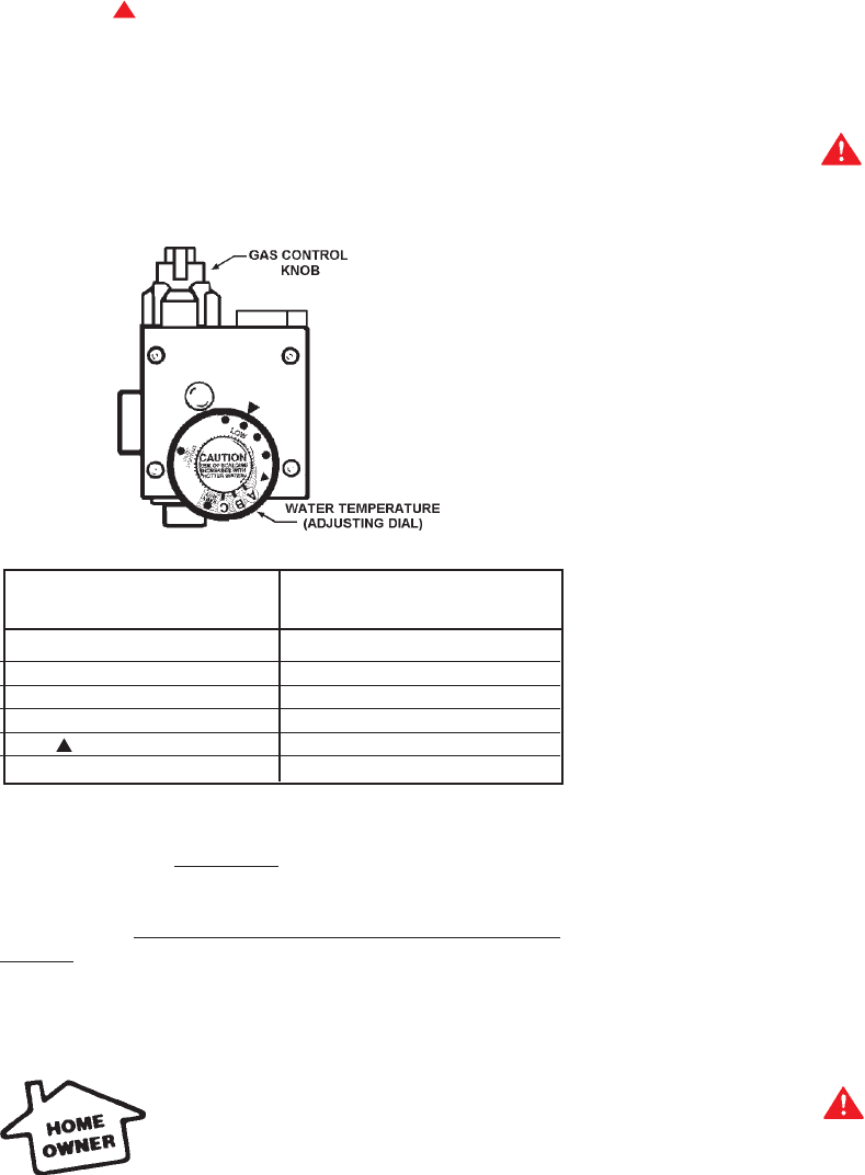
cases, that the water temperature dial, Figure 99, be set for the
lowest temperature which satisfies your hot water needs. This
will also provide the most energy efficient operation of the
water heater. The water temperature adjusting dial was factory
set at the lowest temperature; all the way clockwise to the
mechanical stop. Turning the dial counterclockwise increases
temperature and clockwise reduces temperature.
SETTING THE WATER HEATER TEMPERATURE AT 120°F
(APPROX. “ ” MARK ON FACE OF THERMOSTAT) WILL
REDUCE THE RISK OF SCALDS. Some states require
settings at specific lower temperatures.
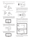
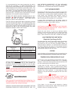
Figure 99 shows the approximate water temperatures produced
at various thermostat dial settings. Short repeated heating cycles
caused by small hot water uses can cause temperatures at the
point of use to exceed the thermostat setting by up to 30°F. If you
experience this type of use you should consider using lower
temperature settings to reduce scald hazards.
Temperature Time to Produce 2nd & 3rd
Setting Degree Burns on Adult Skin
VERY HOT= approx. 160°F About 1/2 second
C = approx. 150°F About 1-1/2 seconds
B = approx. 140°F Less than 5 seconds
A = approx. 130°F About 30 seconds
= approx. 120°F More than 5 minutes
LOW = approx. 80°F
FIGURE 99
Valves for reducing point-of-use temperature by mixing cold and
hot water are available (See Fig. 2). Also available are
inexpensive devices that attach to faucets to limit hot water
temperatures.
Contact a licensed plumber or the local plumbing
authority.
SHOULD OVERHEATING OCCUR OR THE GAS SUPPLY FAIL
TO SHUT OFF, TURN OFF THE MAIN MANUAL GAS CONTROL
VALVE TO THE APPLIANCE (SEE FIGURE 1).
MAINTENANCE
FOR YOUR SAFETY AND SATISFACTORY OPERATION, IT IS
RECOMMENDED THAT THIS HEATER BE CHECKED ONCE A
YEAR BY A COMPETENT SERVICE PERSON.
USERS OF THIS APPLIANCE SHOULD BE AWARE THAT GAS
COMPONENTS WEAR OUT OVER A PERIOD OF TIME. THE
GAS CARRYING COMPONENTS OF THIS APPLIANCE
SHOULD BE INSPECTED FOR PROPER OPERATION
PERIODICALLY BY A QUALIFIED SERVICE TECHNICIAN.
PILOT AND MAIN BURNER
Check pilot and main burner every six months for proper flame
characteristics. This is done by removing door on heater, fig. 1.
The main burner should provide complete combustion of gas;
ignite rapidly; give reasonably quiet operation; cause no
excessive flame lifting from burner ports. Make sure that the
flow of combustion and ventilation air is not blocked.
If proper flame characteristics are not evident, check for
accumulation of lint or other foreign material that restricts or
blocks the air openings in the heater or burner.
WARNING
SOOT BUILD-UP INDICATES A PROBLEM THAT REQUIRES
CORRECTION BEFORE FURTHER USE. CONSULT WITH A
QUALIFIED SERVICE TECHNICIAN.
Should the main burner or burner air openings require
cleaning, turn the gas control knob to “OFF” position and allow
the burner to cool. Remove the burner and clean with a soft
brush. Clean main burner orifice with a suitable soft material.
HIGH TEMPERATURE LIMIT SWITCH
(Single-Use Type Energy Cut Off)
The thermostat has a built-in limit switch which will extinguish
the pilot light in case of excessive water temperatures. The
pilot cannot be relit until the entire thermostat (labeled as
single-use type) is replaced. It is important that a serviceman
be called to determine the reason for limit operation and thus
avoid repeated thermostat replacement. Lower the temperature
adjustment dial setting on the new control.
VENTING
HAVE VENTING SYSTEM CHECKED EVERY SIX MONTHS FOR
OBSTRUCTIONS AND/OR DETERIORATION IN VENT PIPING.
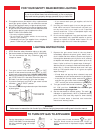
TEMPERATURE & PRESSURE RELIEF VALVE
At least once a year, the temperature and pressure relief valve,
fig. 1. must be checked to ensure that it is in operating
condition. Lift the lever at the top of the valve several times until
the valve seats properly and operates freely.
If water does not flow, remove the valve and inspect for
obstructions or corrosion. Have a qualified servicer replace
with a new valve of the recommended size as necessary. Do
not attempt to repair the valve, as this could result in improper
operation and a tank explosion. In areas with poor water
conditions, it may be necessary to inspect the T&P valve more
frequently.
WARNING
THE WATER PASSING OUT OF THE VALVE DURING THIS
CHECKING OPERATION MAY BE EXTREMELY HOT. AVOID
CONTACT AND DISCHARGE SAFELY TO PREVENT WATER
DAMAGE.
DRAINING
If the heater is to be shut off and exposed to freezing
temperatures, it must be drained. Water, if left in the tank and
allowed to freeze, will damage the heater.