


14
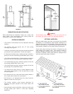
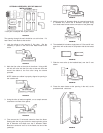
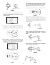
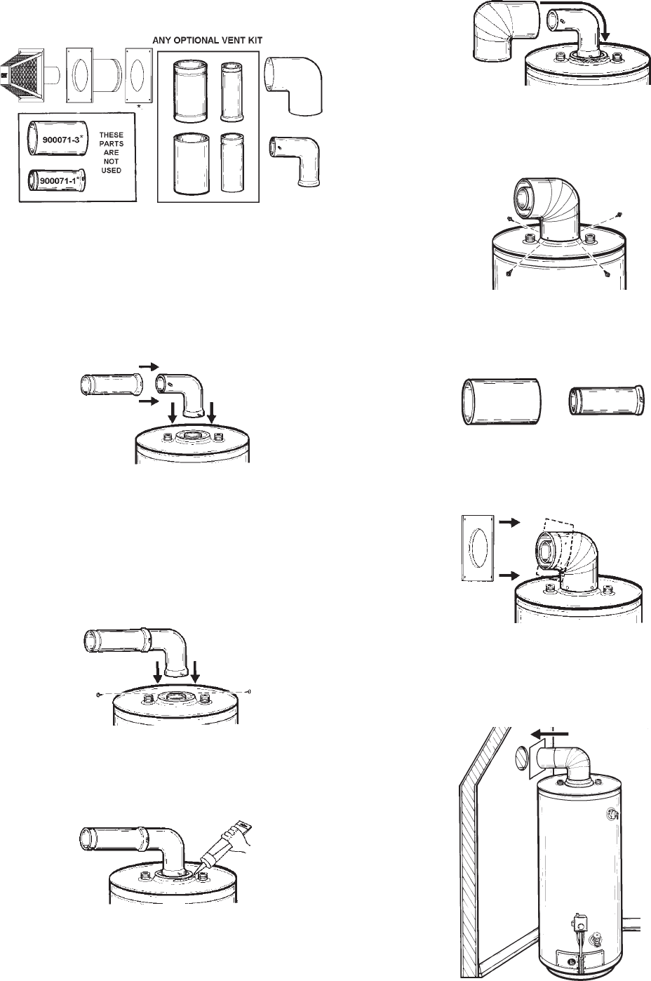
OPTIONAL HORIZONTAL VENT KIT #900124-7
INSTALLATION #3
* Each part is stamped with a part number.
FIGURE 53
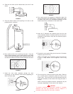
The opening through the wall should be cut at this time. If it
hasn’t been, refer back to that section.
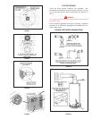
1. Lock the elbow to the straight 3” flue pipe. Set the
assembly in place on the end of the water heater’s flue
collar.
FIGURE 54
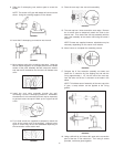
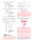
2. Mark the flue collar at the slots in the elbow. Using a #22
drill bit, drill holes into the flue collar at the two slots and
secure the elbow to the flue collar using the screws
provided.
NOTE: Make sure elbow is properly aligned to opening in
the outside wall.
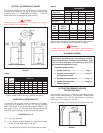
FIGURE 55
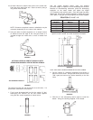
3. Using the tube of sealant supplied, run an ample amount
around the oval flare of the jacket.
FIGURE 56
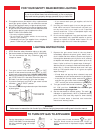
4. First remove the 3” horizontal extension from the elbow.
Starting with the long end (with four securing holes), place
the 6” diameter vent elbow over the 3” diameter elbow.
Bend the round end “oval” to fit the flared oval end of the
jacket top.
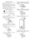
FIGURE 57
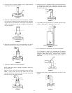
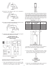
5. Making sure the 6” diameter elbow is centered around the
3” diameter flue, secure the 6” diameter vent pipe using
four sheet metal screws at the connection of the jacket top.
FIGURE 58
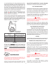
6. The standard kit includes a single piece of 3” flue and 6” vent
pipe which will not be used in conjunction with the horizontal
kit.
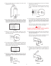
FIGURE 59
7. Slide the vent collar (to be installed later) over the 6” vent
elbow.
FIGURE 60
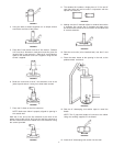
8. Place the water heater at the opening in the wall, at the
predetermined clearance.
FIGURE 61