


18
FIGURE 86
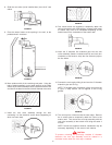
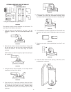
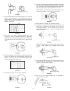
14. Move outdoors with all the remaining vent parts. Using the
tube of sealant supplied, run an ample amount on the
inside surface of the collar assembly that will contact the
exterior wall and also fill the bead on the end of the 6”
diameter vent collar.
FIGURE 87
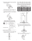
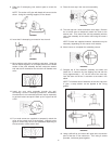
15. Install the vent collar assembly through the wall,
connecting it to the 6” telescoping extension. Remember,
the extension is not connected yet and it may be necessary
to go back indoors and push it back up for a tight fit to the
collar.
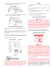
FIGURE 88
16. We have supplied 4 wood screws to temporarily attach the
collar to the exterior wall of the building. However, other
types of screws may have to be substituted depending on
the construction of the exterior wall.
FIGURE 89
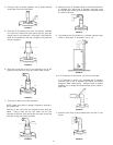
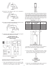
17. Place the vent cap in the vent collar assembly.
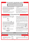
FIGURE 90
18. The vent cap has 4 holes around the outer edge. Remove the
4 screws used to temporarily attach the collar to the exterior
wall. Then secure the vent cap assembly with the vent collar
assembly to the exterior wall using the same 4 screws.
NOTE: Screws are supplied; however, substitution may be
necessary depending on the exterior wall material.
FIGURE 91
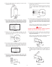
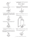
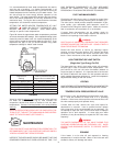
19. Move indoors to complete the assembly process.
20. Collapse the 6” vent extension pipes as shown below and
install the 3” extension by first slipping the end with the
O-ring approximately 1 1/4” into the end of the vent cap.
Lock the other end of the 3” extension assembly to the
studs in the elbow.
FIGURE 92
NOTE: To facilitate ease of assembly of the vent cap to the
3” pipe, a soap solution can be applied to the O-ring
gasket.
FIGURE 93
21. Using a #22 drill bit, drill holes 180° apart at the connection
point of the two 3” flue extensions. Then using 2 screws
provided, lock these pipes together.
FIGURE 94
22. Now the 6” vent extension pipes can be expanded to
connect at the vent elbow.
FIGURE 95