


11
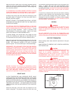
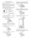
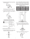
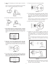
16. Go back indoors to attach inside collar to the inside wall.
Place the collar against the wall. Secure to wall by using 4
long sheet metal screws.
FIGURE 30
NOTE: Screws are supplied; however, substitution may be
necessary depending on the interior wall material.
17. Using the tube of sealant supplied, run an ample amount
of sealant around the edge of the vent pipe where it is
inserted through the inside collar to seal air drafts from
wall.
FIGURE 31
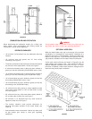
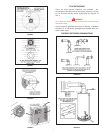
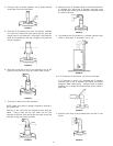
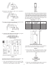
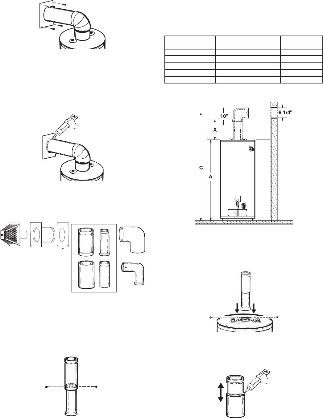
OPTIONAL VERTICAL VENT KIT # 900124-6 WITH
STANDARD HORIZONTAL VENT KIT INSTALLATION #2
FIGURE 32
The opening through the wall should be cut at this time. If it
hasn’t been, refer back to that section.
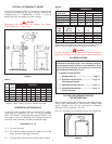
1. First it must be determined how far the vertical (3” dia.)
telescoping flue sections are set and locked together
using the two screws supplied as shown below.
FIGURE 33
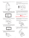
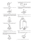
Use the simple equation below, chart and drawing
to find the length of expansion of the telescoping flue sections.
Because of manufacturing tolerances, place the telescoping
extension on the water heater and adjust the height
(“X” Dimension) and mark the point. Once the length has been
determined, lock the two sections together by drilling two holes
(180° apart) in the pipe and securing with the screws supplied.
EQUATION: C - A -10” = X
* See models and rating plate attached to the water heater for
specific model number and other detailed information.
FIGURE 34
NOTE: EACH PART HAS BEEN STAMPED WITH A PART NUMBER.
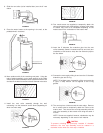
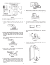
2. Set the vertical (3” diameter) telescoping flue section in
place on the flue collar. Using a #22 drill bit, drill two holes
(180° apart) and secure the vertical assembly to the flue
collar.
FIGURE 35
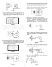
3. Slide the 6” vent telescoping section apart to reveal the
beads. Using the caulking supplied, fill the beads.
FIGURE 36
ANY OPTIONAL VENT KIT
*GALLON *BTU’s in 1000’s
CAPACITY NAT/L.P. A
40 36/36 48-3/4
50 38/38 57-1/2
40 40/40 48-3/4
50 48/44 61
75 55 NAT. 63