


10
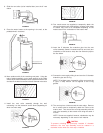
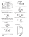
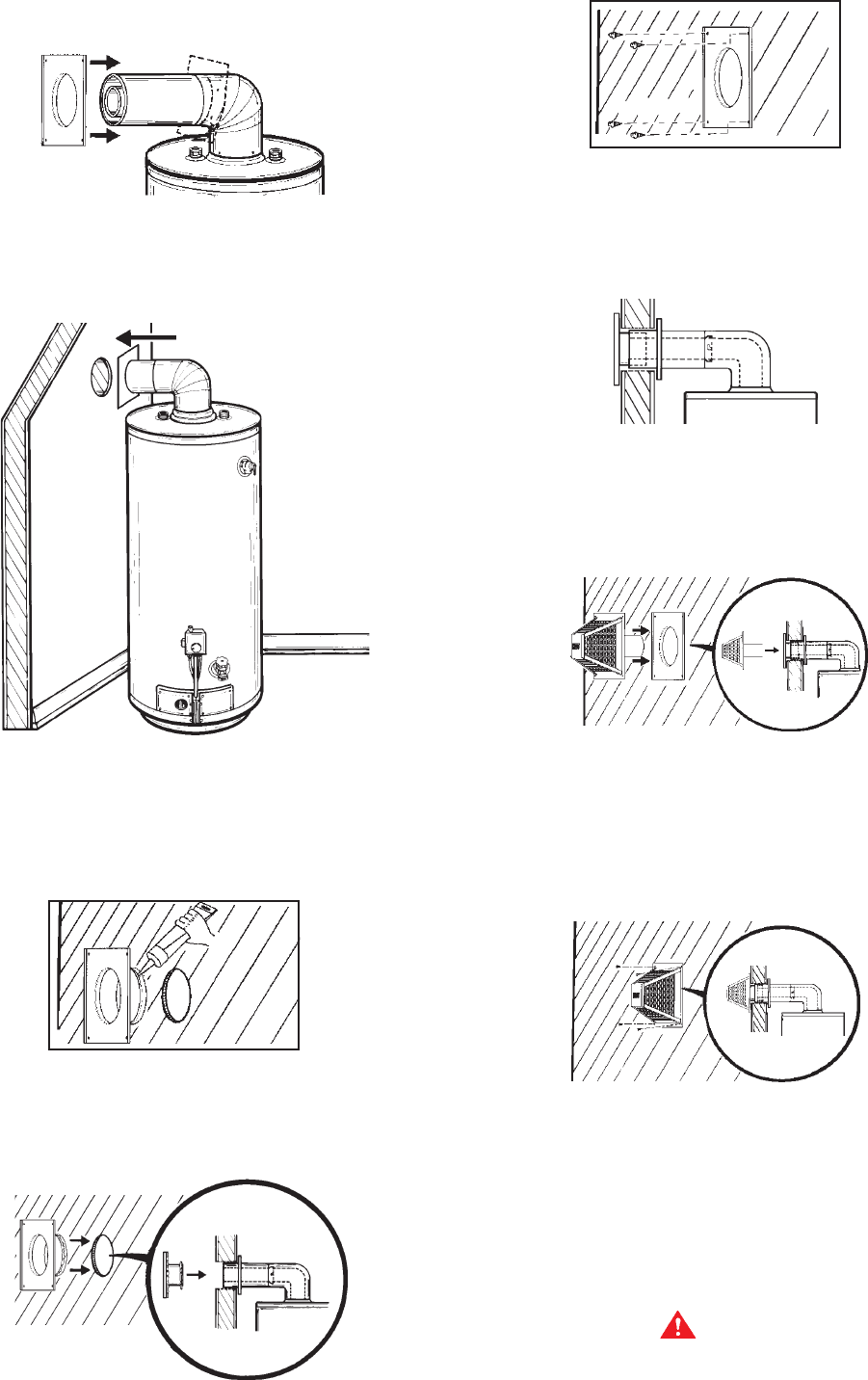
8. Slide the vent collar (to be installed later) over the 6” vent
elbow.
FIGURE 22
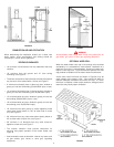
9. Place the water heater at the opening in the wall, at the
predetermined clearance.
FIGURE 23
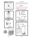
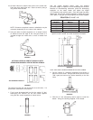
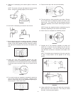
10. Move outdoors with all the remaining vent parts. Using the
tube of sealant supplied, run an ample amount on the inside
surface of the collar assembly that will contact the exterior wall
and also fill the bead on the end of the 6” diameter vent collar.
FIGURE 24
11. Install the vent collar assembly through the wall,
connecting it to the extension and/or elbow (depending on
which one was used).
FIGURE 25
FIGURE 26
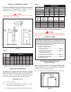
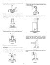
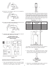
12. Four wood screws are supplied to temporarily attach the
collar to the exterior wall of the building. However, other types
of screws may have to be substituted depending on the
material used in the construction of the exterior wall.
FIGURE 27
13. Insert the 3” diameter flue extension pipe into the vent
collar assembly (flared & notched end first) and lock (turn
clockwise to lock studs to slots) the flue extension pipe to
the flue elbow.
FIGURE 28
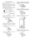
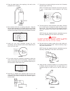
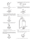
14. Connect the vent cap by sliding its end over the 3” diameter
extension pipe and O-ring.
NOTE: To facilitate ease of assembly of the vent cap to the
3” pipe, a soap solution can be applied to the O-ring
gasket.
FIGURE 29
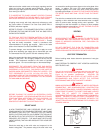
15. The vent cap has 4 holes around the outer edge. Remove
the 4 screws used to temporarily attach the collar to the
exterior wall. Then secure the vent cap assembly with the
vent collar assembly to the exterior wall using the same 4
screws.
NOTE: Screws are supplied; however, substitution may be
necessary depending on the exterior wall material
.
CAUTION
To prevent unlocking the previously installed 3” diameter
extension, the vent cap assembly must be rotated in a
clockwise motion when the vent cap is installed.