


9
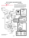
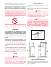
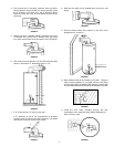
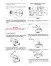
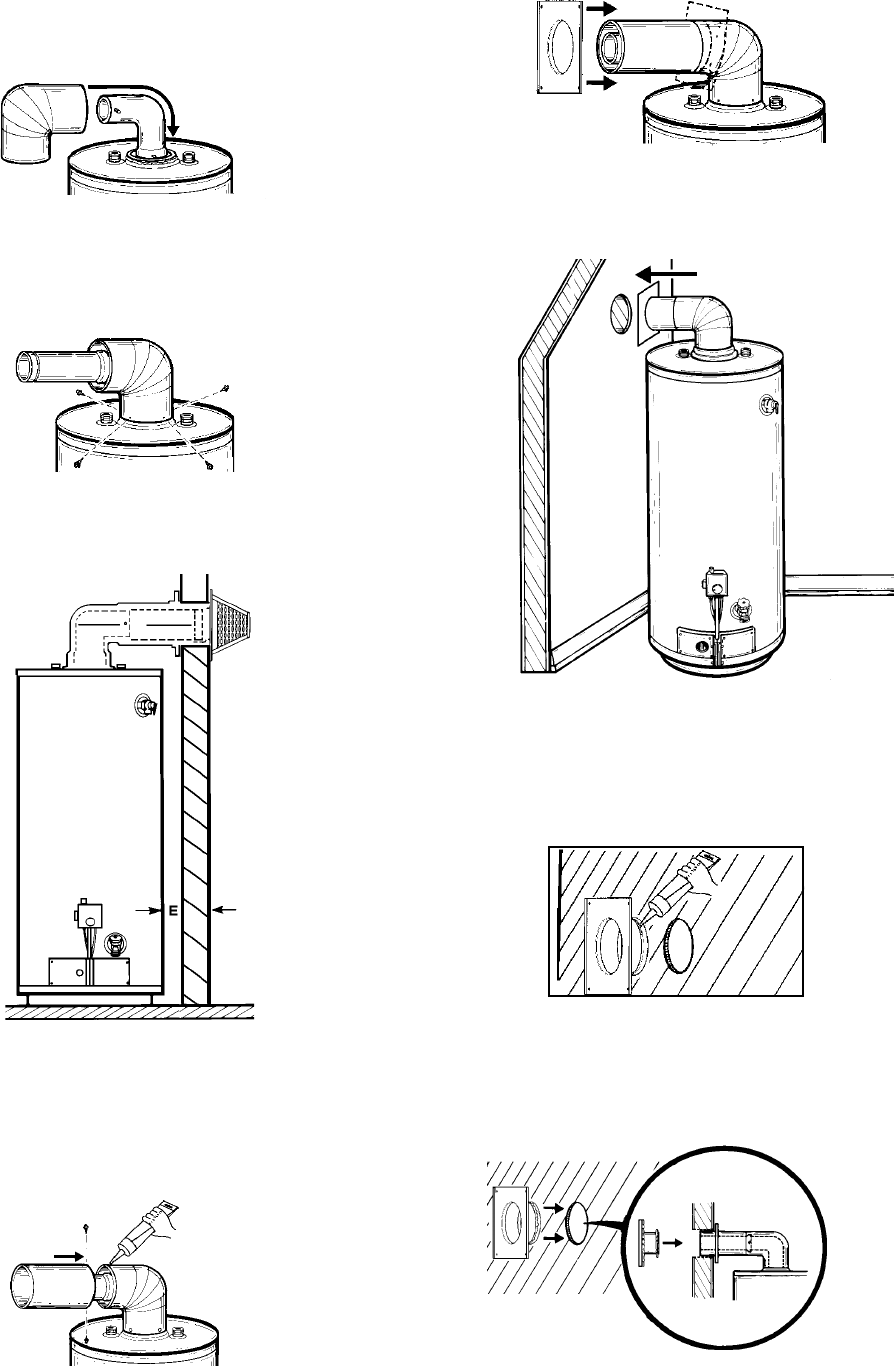
4. First remove the 3” horizontal extension from the elbow.
Starting with the long end (with four securing holes), place
the 6” diameter vent elbow over the 3” diameter elbow.
Bend the round end “oval” to fit the flared oval end of the
jacket top.
FIGURE 18
5. Making sure the 6” diameter elbow is centered around the
3” diameter flue, secure the 6” diameter vent pipe using
four sheet metal screws at the connection of the jacket top.
FIGURE 19
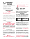
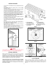
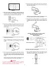
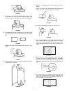
6. The standard vent kit includes a 6” diameter extension pipe
which is used when “E” dimension is over 6 1/2”.
FIGURE 20
7. If “E” is less than 6 1/2” move to next step.
If “E” dimension is over 6 1/2”, assemble the 6” diameter
extension pipe (crimped end) to the 6” diameter vent elbow
and secure using two sheet metal screws.
FIGURE 21
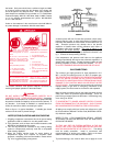
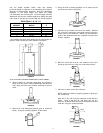
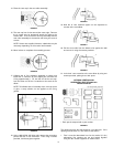
8. Slide the vent collar (to be installed later) over the 6” vent
elbow.
FIGURE 22
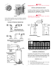
9. Place the water heater at the opening in the wall, at the
predetermined clearance.
FIGURE 23
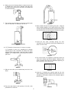
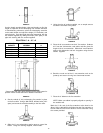
10. Move outdoors with all the remaining vent parts. Using the
tube of sealant supplied, run an ample amount on the inside
surface of the collar assembly that will contact the exterior wall
and also fill the bead on the end of the 6” diameter vent collar.
FIGURE 24
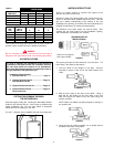
11. Install the vent collar assembly through the wall,
connecting it to the extension and/or elbow (depending on
which one was used).
FIGURE 25