


16
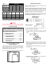
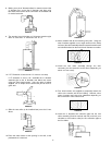
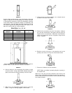
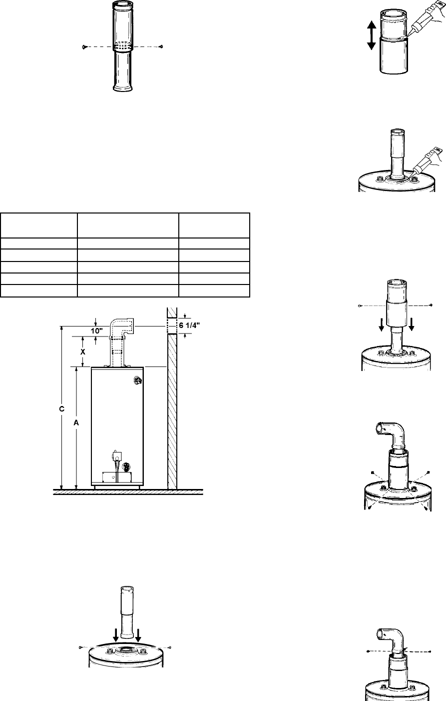
FIGURE 74
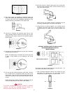
Use the simple equation below, chart and drawing to find the
length of expansion of the telescoping flue sections. Because
of manufacturing tolerances, place the telescoping extension
on the water heater and adjust the height (“X” Dimension) and
mark the point. Once the length has been determined, lock the
two sections together by drilling two holes (180° apart) in the
pipe and securing with the screws supplied.
EQUATION: C - A - 10” = X
* See models and rating plate attached to the water heater for
specific model number and other detailed information.
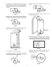
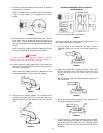
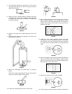
FIGURE 75
2. Set the vertical (3” dia.) telescoping flue section in place
on the flue collar. Using a #22 drill bit, drill two holes (180°
apart) and screw the vertical assembly to the flue collar.
FIGURE 76
3. Slide the 6” vent telescoping section apart to reveal the
beads. Using the caulking supplied, fill the beads.
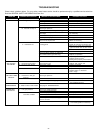
*GALLON *BTU’s in 1000’s
CAPACITY NATURAL A
40 36/36 48-3/4
50 38/38 57-1/2
40 40/44 48-3/4
50 48/44 61
75 55 NAT. 63
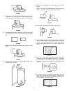
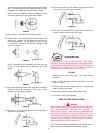
FIGURE 77
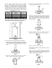
4. Using the tube of sealant supplied, run an ample amount
around the oval flare of the jacket.
FIGURE 78
5. Place the 6” vent section over the 3” flue section. Subtract
3/4” from the X dimension used earlier and this gives the
length of the 3” vent extension. Slide the 6” vent extension
apart to this dimension and lock it together using the two
screws supplied.
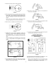
FIGURE 79
6. Bend the round end of the 6” vent extension oval at the
jacket tip and secure it using four sheet metal screws.
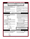
FIGURE 80
7. Place the 3” elbow on the flue extension.
NOTE: Make sure elbow is properly aligned to opening in
the outside wall.
Mark the 3” dia. end of the flue extension at the slots in the
elbow. Using a #22 drill bit, drill holes into the flue extension at
the two slots and secure the elbow to the flue extension using
the screws provided.
FIGURE 81