


15
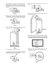
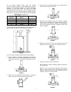
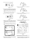
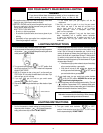
14. Place the vent cap in the vent collar assembly.
FIGURE 67
15. The vent cap has 4 holes around the outer edge. Remove
the 4 screws used to temporarily attach the collar to the
exterior wall. Then secure the vent cap assembly with the
vent collar assembly to the exterior wall using the same 4
screws.
NOTE: Screws are supplied; however, substitution may be
necessary depending on the exterior wall material.
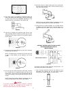
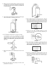
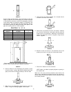
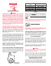
16. Move indoors to complete the assembly process.
FIGURE 68
17. Collapse the 6” flue extension assembly as shown and
install the 3” extension by first slipping the end with the
O-ring approximately 1 1/4” into the end of the vent cap.
Lock the other end of the 3” extension to the studs in the
elbow.
NOTE: To facilitate ease of assembly of the vent cap to the
3” pipe, a soap solution can be applied to the O-ring
gasket.
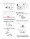
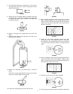
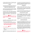
FIGURE 69
18. Using a #22 drill bit, drill holes 180° apart at the connection
point of the two 3” flue extensions. Then using 2 screws
provided, lock these pipes together.
FIGURE 70
19. Now the 6” vent extension pipes can be expanded to
connect at the vent elbow.
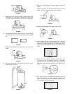
FIGURE 71
20. Pull the vent collar from the elbow to be against the wall
and secure it using the screws provided.
FIGURE 72
21. Lock the 6” vent extension to the vent elbow by using two
screws provided, placing them 180° apart.
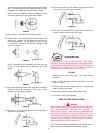
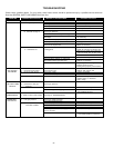
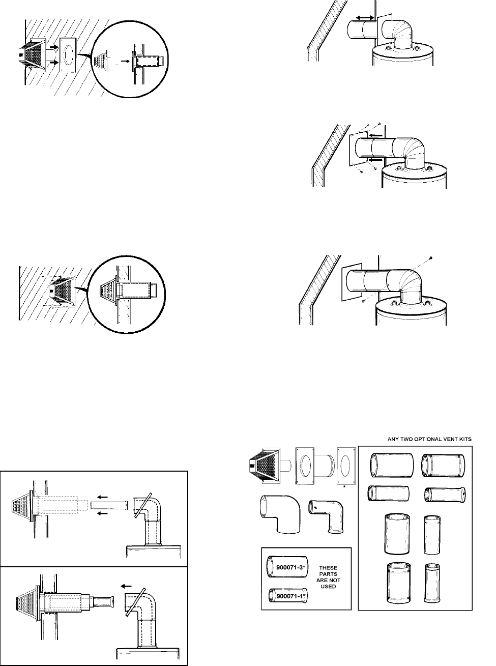
OPTIONAL VERTICAL AND
HORIZONTAL VENT KIT #900124-8
INSTALLATION #4
* Each part is stamped with a part number.
FIGURE 73
The opening through the wall should be cut at this time. If the
opening has not been cut, refer back to that section.
1. First it must be determined how far the vertical (3” dia.)
telescoping flue sections are set and locked together
using the two screws supplied as shown below.