


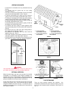
10
FIGURE 26
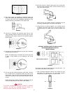
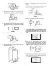
12. Four wood screws are supplied to temporarily attach the
collar to the exterior wall of the building. However, other types
of screws may have to be substituted depending on the
material used in the construction of the exterior wall.
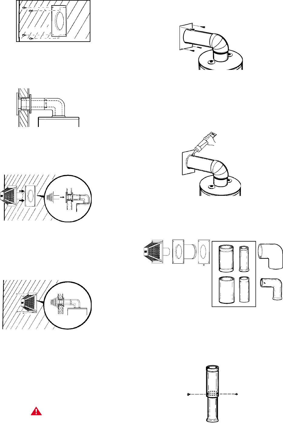
FIGURE 27
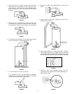
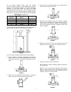
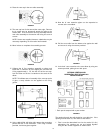
13. Insert the 3” diameter flue extension pipe into the vent
collar assembly (flared & notched end first) and lock (turn
clockwise to lock studs to slots) the flue extension pipe to
the flue elbow.
FIGURE 28
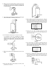
14. Connect the vent cap by sliding its end over the 3” diameter
extension pipe and O-ring.
NOTE: To facilitate ease of assembly of the vent cap to the
3” pipe, a soap solution can be applied to the O-ring
gasket.
FIGURE 29
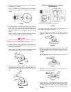
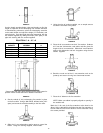
15. The vent cap has 4 holes around the outer edge. Remove
the 4 screws used to temporarily attach the collar to the
exterior wall. Then secure the vent cap assembly with the
vent collar assembly to the exterior wall using the same 4
screws.
NOTE: Screws are supplied; however, substitution may be
necessary depending on the exterior wall material
.
CAUTION
To prevent unlocking the previously installed 3” diameter
extension, the vent cap assembly must be rotated in a
clockwise motion when the vent cap is installed.
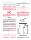
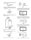
16. Go back indoors to attach inside collar to the inside wall.
Place the collar against the wall. Secure to wall by using 4
long sheet metal screws.
FIGURE 30
NOTE: Screws are supplied; however, substitution may be
necessary depending on the interior wall material.
17. Using the tube of sealant supplied, run an ample amount
of sealant around the edge of the vent pipe where it is
inserted through the inside collar to seal air drafts from
wall.
FIGURE 31
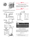
OPTIONAL VERTICAL VENT KIT # 900124-6 WITH
STANDARD HORIZONTAL VENT KIT
INSTALLATION #2
ANY OPTIONAL VENT KIT
FIGURE 32
The opening through the wall should be cut at this time. If it
hasn’t been, refer back to that section.
1. First it must be determined how far the vertical (3” dia.)
telescoping flue sections are set and locked together
using the two screws supplied as shown below.
FIGURE 33