


7
THERMOMETERS (Not Supplied)
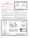
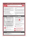
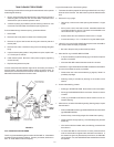
Thermometers should be obtained and field installed as shown in Figure 3.
Thermometers are installed in the system as a means of detecting the
temperature of the outlet water supply.
COMBINATION WATER (POTABLE) HEATING
AND SPACE HEATING
1. All piping components connected to this unit for space heating
applications shall be suitable for use with potable water.
2. Toxic chemicals, such as those used for boiler treatment, shall NEVER
be introduced into this system.
3. This unit may NEVER be connected to any existing heating system or
component(s) previously used with a non-potable water heating
appliance.
4. When the system requires water for space heating at temperatures
higher than required for domestic water purposes, a tempering valve
must be installed. Please refer to installation diagram on page 6 of
this manual for suggested piping arrangements.
CAUTION
A closed system will exist if a check valve (without bypass), pressure
reducing valve (without bypass), or a water meter (without bypass) is
installed in the cold water line between the water heater and street main
(or well).
Excessive pressure may develop in such closed systems, causing
premature tank failure or intermittent relief valve operation.
This is not a
warranty failure. An expansion tank or a similar device may be required in
the inlet supply line between the appliance and the meter or valve to
compensate for the thermal expansion of the water.
SYSTEM CONNECTIONS
The system installation must conform to these instructions and to the local
code authority having jurisdiction. Good practice requires that all heavy
piping be supported.
RELIEF VALVE
This water heater is equipped with a combination temperature-pressure
relief valve that complies with the standard for relief valves and automatic
gas shutoff devices for hot water supply system, ANSI Z21.22, for Canada
see CAN/CSA B149.1-00. FOR SAFE OPERATION OF THE WATER HEATER,
THE RELIEF VALVE(S) MUST NOT BE REMOVED OR PLUGGED.
ASME ratings cover pressure relief capacities. A.G.A. ratings cover release
rate with temperature actuation.
In addition to the appliance relief valve, each remote storage tank which
may be used in conjunction with this appliance shall also be installed with
a properly sized, rated and approved combination temperature (ANSI) and
pressure (ASME) relief valve(s). This valve shall comply with the standard
for relief valves and automatic gas shutoff devices for hot water supply
systems. ANSI Z21.22.
WARNING
THE PURPOSE OF RELIEF VALVE IS TO AVOID EXCESSIVE PRESSURE
OR TEMPERATURE INTO THE STEAM RANGE, WHICH MAY CAUSE
SCALDING AT FIXTURES, TANK EXPLOSION, SYSTEM OR HEATER
DAMAGE. NO VALVE IS TO BE PLACED BETWEEN THE RELIEF VALVE
AND TANK.
Your local code authority may have other specific relief valve requirements.
A DRAIN LINE MUST BE CONNECTED TO THE RELIEF VALVE TO DIRECT
DISCHARGE TO A SAFE LOCATION TO AVOID SCALDING OR WATER
DAMAGE. THIS LINE MUST NOT BE REDUCED FROM THE SIZE OF THE
VALVE OUTLET AND MUST NOT CONTAIN VALVES, RESTRICTIONS NOR
SHOULD IT BE LOCATED IN FREEZING AREAS. DO NOT THREAD OR CAP
THE END OF THIS LINE. RESTRICTED OR BLOCKED DISCHARGE WILL
DEFEAT THE PURPOSE OF THE VALVE AND IS UNSAFE. DISCHARGE LINE
SHALL BE INSTALLED TO ALLOW COMPLETE DRAINAGE OF BOTH THE
VALVE AND LINE.
See SERVICE INFORMATION section for procedure and precautions.
The type, size and location of the relief valves must be in accordance with
local codes. The location of the relief valve is shown in Figure 1. The
heater has a factory installed high temperature limit switch.
GAS PIPING
Contact your local gas service company to ensure that adequate gas
service is available and to review applicable installation codes for your
area.
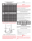
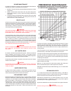
Size the main gas line in accordance with Table 4. The figures shown are
for straight lengths of pipe at 0.5 in. W.C. pressure drop, which is considered
normal for low pressure systems. Note: Fittings such as elbows, tees and
line regulators will add to the pipe pressure drop. Also refer to the latest
version of the National Fuel Gas Code. For Canadian installations consult
Canadian Installation Code CAN/CSA B149.1-00.
WARNING
THE HEATER IS NOT INTENDED FOR OPERATION AT HIGHER THAN 14.0"
W.C.(3.48 Kpa) - NATURAL GAS SUPPLY GAS PRESSURE. EXPOSURE TO
HIGHER SUPPLY PRESSURE MAY CAUSE DAMAGE TO THE GAS VALVE
WHICH COULD RESULT IN FIRE OR EXPLOSION. IF OVERPRESSURE HAS
OCCURRED SUCH AS THROUGH IMPROPER TESTING OF GAS LINES OR
EMERGENCY MALFUNCTION OF THE SUPPLY SYSTEM, THE GAS VALVE
MUST BE CHECKED FOR SAFE OPERATION. MAKE SURE THAT THE
OUTSIDE VENTS ON THE SUPPLY REGULATORS AND THE SAFETY VENT
VALVES ARE PROTECTED AGAINST BLOCKAGE. THESE ARE PARTS OF
THE GAS SUPPLY SYSTEM, NOT THE HEATER. VENT BLOCKAGE MAY
OCCUR DURING ICE STORMS.
IT IS IMPORTANT TO GUARD AGAINST GAS VALVE FOULING FROM
CONTAMINANTS IN THE GAS WAYS. SUCH FOULING MAY CAUSE
IMPROPER OPERATION, FIRE OR EXPLOSION.
IF COPPER SUPPLY LINES ARE USED THEY MUST BE INTERNALLY TINNED
AND CERTIFIED FOR GAS SERVICE. BEFORE ATTACHING THE GAS LINE,
BE SURE THAT ALL GAS PIPE IS CLEAN ON THE INSIDE.
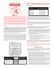
TO TRAP ANY DIRT OR FOREIGN MATERIAL IN THE GAS SUPPLY LINE, A
DIRT LEG (SOMETIMES CALLED SEDIMENT TRAP OR DRIP LEG) MUST BE
INCORPORATED IN THE PIPING (SEE FIG. 5). THE DIRT LEG MUST BE
READILY ACCESSIBLE AND NOT SUBJECT TO FREEZING CONDITIONS.
INSTALL IN ACCORDANCE WITH RECOMMENDATIONS OF SERVING GAS
SUPPLIERS. REFER TO THE LATEST VERSION OF THE
NATIONAL FUEL
GAS CODE. For Canadian installations consult Canadian Installation Code
CAN/CSA B149.1-00.
To prevent damage, care must be taken not to apply too much torque when
attaching gas supply pipe to gas valve inlet.
Apply joint compounds (pipe dope) sparingly and only to the male threads
of pipe joints. Do not apply compounds to the first two threads. Use
compounds resistant to the action of liquefied petroleum gases.