


5
(45.7 CM) OR MORE ABOVE THE FLOOR. THIS MAY REDUCE THE RISK IF
LOCATION IN SUCH AN AREA CANNOT BE AVOIDED.
DO NOT INSTALL THIS WATER HEATER DIRECTLY ON A CARPETED
FLOOR. A FIRE HAZARD MAY RESULT. Instead the water heater must
be placed on a metal or wood panel extending beyond the full width and
depth by at least 3 inches (7.6 CM) in any direction. If the heater is installed
in a carpeted alcove or closet, the entire floor shall be covered by the panel.
Also, see the drain requirements.
THIS HEATER SHALL BE LOCATED OR PROTECTED SO IT IS NOT
SUBJECT TO PHYSICAL DAMAGE BY A MOVING VEHICLE.
WARNING
FLAMMABLE ITEMS, PRESSURIZED CONTAINERS OR ANY OTHER
POTENTIAL FIRE HAZARDOUS ARTICLES MUST NEVER BE PLACED
ON OR ADJACENT TO THE HEATER. OPEN CONTAINERS OF
FLAMMABLE MATERIAL SHOULD NOT BE STORED OR USED IN THE
SAME ROOM WITH THE HEATER.
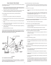
When installing the heater, consideration must be given to proper location.
Location selected should be as close to the stack or chimney as practicable,
with adequate air supply and as centralized with the piping system as
possible.
THE HEATER MUST NOT BE LOCATED IN AN AREA WHERE IT WILL
BE SUBJECT TO FREEZING.
THE HEATER SHOULD BE LOCATED IN AN AREA WHERE LEAKAGE
FROM THE HEATER OR CONNECTIONS WILL NOT RESULT IN
DAMAGE TO THE ADJACENT AREA OR TO LOWER FLOORS OF THE
STRUCTURE.
WHEN SUCH LOCATIONS CANNOT BE AVOIDED, A SUITABLE DRAIN
PAN SHOULD BE INSTALLED UNDER THE HEATER. Such pans should
be fabricated with sides at least 2" (5cm) deep, with length and width at
least 2" (5cm) greater than the diameter of the heater and must be piped to
an adequate drain. The pan must not restrict combustion air flow.
Drain pans suitable for these heaters are available from your distributor or
A. O. Smith Water Products Company, 5621 West 115th Street, Alsip, IL
60803. In Canada, A.O. Smith Enterprises, Ltd., P.O. Box 310-768 Erie
Street, Stratford, Ontario N5A 6T3.
For appliance installation locations with elevations above 2000 feet (610
meters), refer to HIGH ALTITUDE INSTALLATIONS section of this manual
for input reduction procedure.
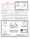
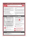
CLEARANCES
These heaters are approved for installation on combustible flooring in a
closet having a ceiling 12" (30.5cm) above top cover and with clearances
to combustible construction of 6" (15.2cm) from flue or vent connector, 0"
(0cm) at the sides and rear and 5" (10.2cm) to front to prevent a possible
fire hazard condition. A minimum of 4" (10.2cm) shall be allowed for
installation of serviceable parts.
HARD WATER
Where hard water conditions exist, water softening or the threshold type of
water treatment is recommended. This will protect the dishwashers, coffee
urns, water heaters, water piping and other equipment.
See MAINTENANCE section for details of tank cleanout procedure.
AIR REQUIREMENTS
REFER TO THE LATEST EDITION OF THE "NATIONAL FUEL GAS CODE
ANSI Z223.1/NFPA 54. FOR CANADA CONSULT CAN/CSA B149.1 -00.
KEEP APPLIANCE AREA CLEAR AND FREE OF COMBUSTIBLE
MATERIALS, GASOLINE AND OTHER FLAMMABLES, VAPORS AND
LIQUIDS.
DO NOT OBSTRUCT THE FLOW OF COMBUSTION OR VENTILATING AIR.
WARNING
ATTIC AND/OR EXHAUST FANS OPERATING ON THE PREMISES WITH A
WATER HEATER CAN RESULT IN CARBON MONOXIDE POISONING AND
DEATH.
OPERATION OF THESE FANS CAN PRODUCE A NEGATIVE DRAFT
IN THE AREA OF THE WATER HEATER PREVENTING THE PRODUCTS
OF COMBUSTION FROM EXHAUSTING THROUGH THE CHIMNEY OR
VENT PIPE.
The venting of the water heater should be inspected by a qualified service
technician at the time of installation and periodically thereafter to ensure a
down-draft condition does not exist.
WARNING
FOR SAFE OPERATION PROVIDE ADEQUATE AIR FOR COMBUSTION AND
VENTILATION. AN INSUFFICIENT SUPPLY OF AIR WILL CAUSE
RECIRCULATION OF COMBUSTION PRODUCTS RESULTING IN AIR
CONTAMINATION THAT MAY BE HAZARDOUS TO LIFE. SUCH A CONDITION
OFTEN WILL RESULT IN A YELLOW, LUMINOUS BURNER FLAME, CAUSING
CARBONING OR SOOTING OF THE COMBUSTION CHAMBER, BURNERS
AND FLUE TUBES AND CREATES A RISK OF ASPHYXIATION.
Where an exhaust fan is supplied in the same room with a heater, sufficient
openings for air must be provided in the walls. UNDERSIZED OPENINGS
WILL CAUSE AIR TO BE DRAWN INTO THE ROOM THROUGH THE CHIMNEY,
CAUSING POOR COMBUSTION. SOOTING MAY RESULT IN SERIOUS
DAMAGE TO THE HEATER AND RISK OF FIRE OR EXPLOSION.
DO NOT OBSTRUCT THE FLOW OF COMBUSTION AND VENTILATING AIR.
ADEQUATE AIR FOR COMBUSTION AND VENTILATION MUST BE PROVIDED
FOR SAFE OPERATION.
UNCONFINED SPACE
In buildings of conventional frame, brick, or stone construction, unconfined
spaces may provide adequate air for combustion, ventilation and draft hood
dilution.
If the unconfined space is within a building of tight construction (buildings
using the following construction: weather stripping, heavy insulation,
caulking, vapor barrier, etc.), air for combustion, ventilation and draft hood
dilution must be obtained from outdoors. The installation instructions for
confined spaces in tightly constructed buildings must be followed to ensure
adequate air supply.
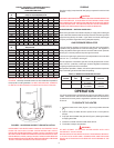
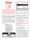
CONFINED SPACE
When drawing combustion and dilution air from inside a conventionally
constructed building to a confined space, such a space shall be provided
with two permanent openings, ONE IN OR WITHIN 12 INCHES (30.5cm)
OF THE ENCLOSURE TOP AND ONE IN OR WITHIN 12 INCHES
(30.5cm) OF THE ENCLOSURE BOTTOM. Each opening shall have a
free area of at least one square inch per 1000 Btuh (2,225mm
2
/Kw) of the
total input of all appliances in the enclosure, but not less than 100 square
inches (645 square cm).
If the confined space is within a building of tight construction, air for
combustion, ventilation, and draft hood dilution must be obtained from
outdoors. When directly communicating with the outdoors or
communicating with the outdoors through vertical ducts, two permanent
openings, located in the above manner, shall be provided. Each opening
shall have a free area of not less than one square inch per 4000 Btuh
(8,900mm
2
/Kw) of the total input of all appliances in the enclosure. If
horizontal ducts are used, each opening shall have a free area of not less
than one square inch per 2000 Btuh (4,450mm
2
/Kw) of the total input of all
appliances in the enclosure. For Canadian installations consult CAN/CSA
B149.1-00.