


2
FOREWORD
The design of models BTI-80 and 100 comply with the latest version of
ANSI Z21.10.3/CSA 4.3 as automatic storage or automatic circulating tank
type water heaters.
Installation diagrams are found in this manual. These diagrams will serve
to provide the installer with a reference for the materials and method of
piping necessary. It is highly essential that all water and gas piping be
installed as shown on the diagrams.
In addition to these instructions, the equipment shall be installed in
accordance with those installation regulations in force in the local area
where the installation is to be made. These shall be carefully followed in
all cases. Authorities having jurisdiction should be consulted before
installations are made.
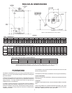
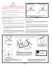
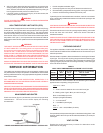
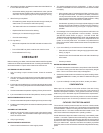
ROUGH-IN DIMENSIONS
FIGURE 1
The installation must conform to these instructions and the local code
authority having jurisdiction.
In the absence of local codes, the installation must comply with the following:
In the United States:
National Fuel Gas Code, ANSI Z223.1 / NFPA 54 and the National Electric
Code, NFPA 70;
In Canada:
Installation Code CAN/CSA B149.1-00 and the Canadian Electric Code CSA
C22.1.
These are available from Canadian Standards Association, 8501 East
Pleasant Valley Road, Cleveland, OH 44131 or National Fire Protection
Association, 1 Batterymarch Park, Quincy, MA 02269.
*INSTALL IN ACCORDANCE WITH LOCAL CODES
TOP VIEW
TABLE 1, DIMENSIONS
ABCDEFGHJKLM
MODEL In. mm In. mm In. mm In. mm In. mm In. mm In. mm In. mm In. mm In. mm In. mm In. mm
BTI-80 66 5/16 1684 58 1/2 1486 29 5/8 753 25 3/8 645 17 1/4 438 4 102 14 356 16 406 1 1/4 32 1 25 1/2 13 11 15/16 303
BTI-100 71 1/4 1810 66 1/2 1689 30 3/4 781 26 1/2 673 17 1/4 438 4 102 14 1/2 368 16 406 1 1/4 32 1 1/4 32 1/2 13 11 15/16 303
TABLE 3, GAS AND ELECTRICAL CHARACTERISTICS
Manifold Pressure Electrical Characteristics
MODEL Type of Gas Inches W.C. kPa Volts/Hz Amperes
BTI (80, 100) Natural Gas 3.5 0.87 120/60 <5
All Models:Maximum supply pressure = 14.0 in. W.C. (3.48 kPa)
Minimum supply pressure, Natural gas = 4.5 in. W.C. (1.12 kPa), Propane gas = 11.0 in. W.C. (2.74 kPa).
Minimum pressures must be maintained under both load and no load (static and dynamic) conditions.
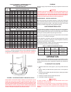
TABLE 2, RECOVERY CAPACITIES (based on 80% thermal efficiency)
U.S. Gallons/Hr and Litres/Hr at TEMPERATURE RISE INDICATED
INPUT F° 30F° 36F° 40F° 50F° 54F° 60F° 70°F° 72F° 80F° 90F° 100F° 108F° 110F° 120F° 126F° 130F° 140F°
MODEL BTUH KW C° 17C° 20C° 23C° 28C° 30C° 33C° 39C° 40C° 44C° 50C° 56C° 60C° 61C° 67C° 70C° 72C° 78C°
BTI-80 76,500 GPH 247 206 185 148 137 124 106 103 93 82 74 68 67 62 59 57 53
22.4 LPH 931 779 700 560 518 469 401 389 352 310 280 257 253 234 223 215 200
BTI-100 90,000 GPH 291 242 218 175 162 145 125 121 109 97 87 81 79 73 69 67 62
26.4 LPH 1104 915 825 662 613 548 473 457 412 367 329 306 299 276 261 253 234
Recovery capacity based on 80% thermal efficiency.