


9
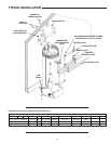
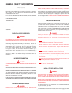
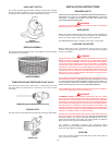
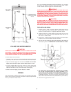
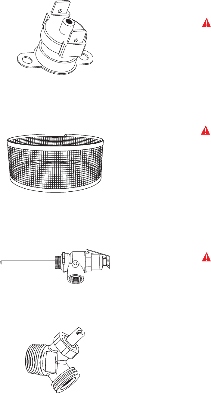
HIGH LIMIT SWITCH
The surface mounted high limit switch monitors the flue gases escaping
through the blower assembly to ensure the temperatures do not exceed
the rating for the CPVC/PVC vent pipe utilized on the venting.
FIGURE 4
HIGH LIMIT SWITCH
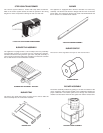
SHROUD ASSEMBLY
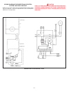
The shroud assembly protects the top of the appliance where the blower
and junction box are located.
SHROUD ASSEMBLY
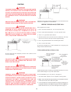
TEMPERATURE AND PRESSURE RELIEF VALVE
The temperature and pressure relief valve is a mechanical valve that
will open when the temperature or pressure in the tank exceeds
safe limits.
TEMPERATURE AND PRESSURE RELIEF VALVE
DRAIN VALVE
The drain valve is used to drain the unit of water for servicing or replacement.
DRAIN VALVE
INSTALLATION INSTRUCTIONS
REQUIRED ABILITY
INSTALLATION OR SERVICE OF THIS WATER HEATER REQUIRES ABILITY
EQUIVALENT TO THAT OF A LICENSED TRADESMAN IN THE FIELD
INVOLVED. PLUMBING, AIR SUPPLY, VENTING, GAS SUPPLY AND
ELECTRICAL WORK ARE REQUIRED.
WARNING
FAILURE TO FOLLOW THESE INSTRUCTIONS CAN RESULT IN SERIOUS
PERSONAL INJURY OR DEATH.
HARD WATER
Where hard water conditions exist, water softening or the threshold type
of water treatment is recommended. This will protect the dishwashers,
coffee urns, water heaters, water piping and other equipment.
See MAINTENANCE section for details of tank clean out procedure.
LOCATING THE HEATER
When installing the heater, consideration must be given to proper
location with adequate air supply and as centralized with the piping
system as possible.
WARNING
THERE IS A RISK IN USING FUEL BURNING APPLIANCES SUCH AS GAS
WATER HEATERS IN ROOMS, GARAGES OR OTHER AREAS WHERE
GASOLINE, OTHER FLAMMABLE LIQUIDS OR ENGINE DRIVEN EQUIPMENT
OR VEHICLES ARE STORED, OPERATED OR REPAIRED. FLAMMABLE
VAPORS ARE HEAVY AND TRAVEL ALONG THE FLOOR AND MAY BE
IGNITED BY THE HEATER’S PILOT OR MAIN BURNER FLAMES CAUSING
FIRE OR EXPLOSION. SOME LOCAL CODES PERMIT OPERATION OF GAS
APPLIANCES IN SUCH AREAS IF THEY ARE INSTALLED 18” OR MORE
ABOVE THE FLOOR. THIS MAY REDUCE THE RISK IF LOCATION IN SUCH
AN AREA CANNOT BE AVOIDED.
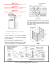
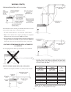
DO NOT INSTALL THIS WATER HEATER DIRECTLY ON A CARPETED FLOOR. A
FIRE HAZARD MAY RESULT. Instead the water heater must be placed on a metal
or wood panel extending beyond the full width and depth by at least 3 inches (7.6
cm) in any direction. If the heater is installed in a carpeted alcove, the entire floor
shall be covered by the panel. Also, see the DRAIN REQUIREMENTS.
THE HEATER SHALL BE LOCATED OR PROTECTED SO IT IS NOT SUBJECT
TO PHYSICAL DAMAGE BY A MOVING VEHICLE.
WARNING
FLAMMABLE ITEMS, PRESSURIZED CONTAINERS OR ANY OTHER
POTENTIAL FIRE HAZARDOUS ARTICLES MUST NEVER BE PLACED ON
OR ADJACENT TO THE HEATER. OPEN CONTAINERS OR FLAMMABLE
MATERIAL SHOULD NOT BE STORED OR USED IN THE SAME ROOM WITH
THE HEATER. THE HEATER MUST NOT BE LOCATED IN AN AREA WHERE IT
WILL BE SUBJECT TO FREEZING. LOCATE IT NEAR A FLOOR DRAIN. THE
HEATER SHOULD BE LOCATED IN AN AREA WHERE LEAKAGE FROM THE
HEATER OR CONNECTIONS WILL NOT RESULT IN DAMAGE TO THE ADJACENT
AREA OR TO LOWER FLOORS OF THE STRUCTURE.
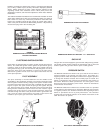
WHEN SUCH LOCATIONS CANNOT BE AVOIDED, A SUITABLE DRAIN PAN
SHOULD BE INSTALLED UNDER THE HEATER. Such pans should be fabricated
with sides at least 2" (5 cm) deep, with length and width at least 2" (5 cm)
greater than the diameter of the heater and must be piped to an adequate
drain. The pan must not restrict combustion air flow.
For appliance installation locations with elevations above
2000 feet (610 m), refer to HIGH ALTITUDE INSTALLATIONS section of this
manual for input reduction procedure.
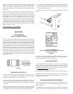
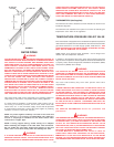
LEVELING
If the unit is not level, insert the bolts which were used in crating into the
legs to correct this condition.