


16
VENTING (CONT'D)
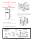
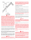
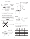
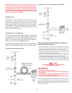
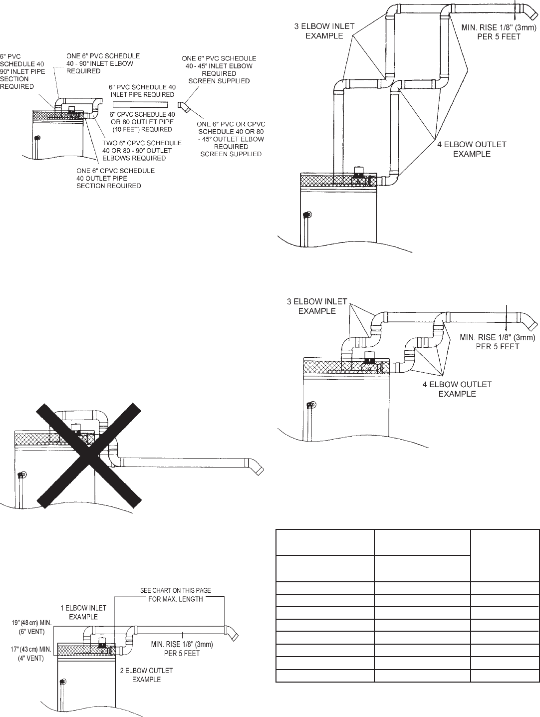
TYPICAL INSTALLATION - UP TO 110' (33.5 m)
Follow illustration above if making an immediate horizontal run of vent
off the blower fittings on top of the water heater.
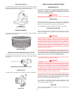
1. The water heater requires its own (separate) venting system.
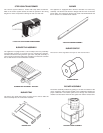
2. Only 6" CPVC Schedule 40 or 80 piping and fittings are acceptable
materials for the first ten feet of the outlet vent system.
3. 6" PVC Schedule 40 or CPVC Schedule 40 or 80 piping and fittings are
acceptable materials for the inlet vent system and for the outlet vent
system after the first ten feet. See vent length chart on this page.
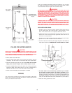
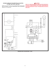
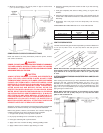
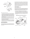
VENTING SYSTEM EXAMPLE INSTALLATIONS FOR
ALL MODELS
The vent piping cannot under any circumstances be run downhill.
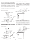
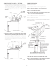
THE VENT PIPING CAN BE INSTALLED AS FOLLOWS:
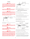
1. Horizontal runs require a minimum 1/8" (3 mm) rise per five feet.
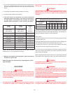
2. The total vertical and horizontal run cannot exceed the maximum
length with number of 90° elbows as specified in the tables below.
If more elbows are required, the venting distance must be reduced
5' (1.5 m) for every 90° elbow:
MODEL MODEL NUMBER
100-400 100-400
OF
90° DEG.
4" DIA. VENT 6" DIA. VENT
ELBOWS*
MAX. LENGTH MAX. LENGTH
45' (13.7 m) 110' (33.5 m) 1
40' (12 m) 105' (32 m) 2
35' (11 m) 100' (30.5 m) 3
30' (9 m) 95' (29 m) 4
25' (7.6 m) 90' (27.4 m) 5
20' (6 m) 85' (26 m) 6
15' (4.6 m) 80' (24.4 m) 7
10' (3 m) 75' (23 m) 8
*NOTE: Two 45° elbows are equivalent to one 90° elbow. One 90°
elbow equals 5' (1.5 m) equivalent vent length.