


20
gas control valve could result in a fire or explosion from
leaking gas.
WARNING
If the main gas line shutoff serving all gas appliances is used,
also turn “OFF” the gas at each appliance. Leave all gas
appliances shut off until the water heater installation is
complete.
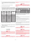
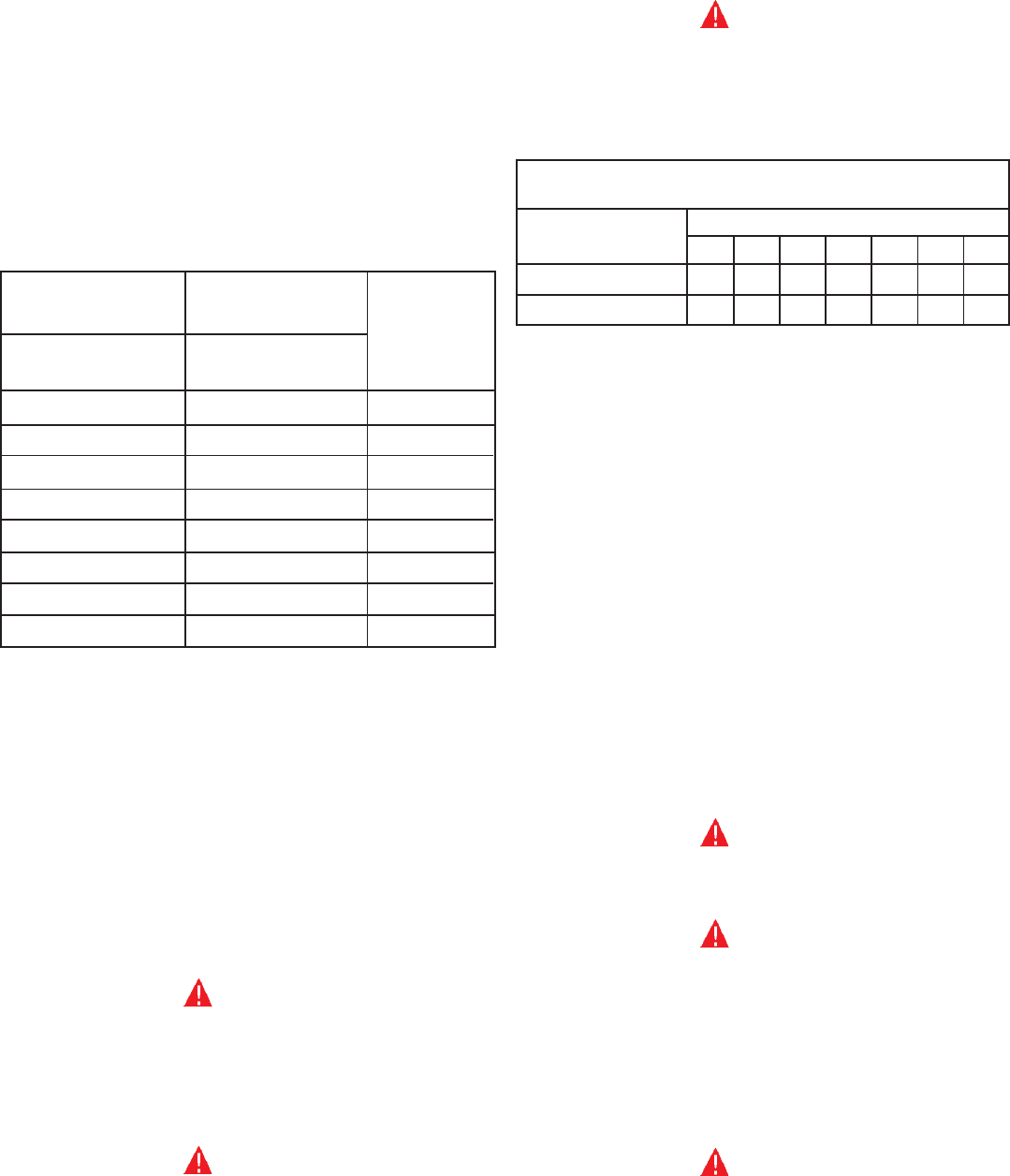
CORRECT GAS PIPE SIZE FOR
WATER HEATERS OPERATING ON NATURAL GAS
TOTAL INPUT DISTANCE TO METER, IN FEET
BTU/HR 30 60 90 120 150 180 210
300,000 1 1/4 1 1/4 1 1/4 1 1/2 1 1/2 1 1/2 1 1/2
400,000 1 1/4 1 1/2 1 1/2 1 1/2 2 2 2
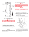
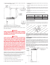
A gas line of sufficient size must be run to the water heater. Consult the
current edition of National Fuel Gas Code ANSI Z223.1, also referred to as
NFPA 54 and the gas company concerning pipe size.
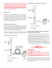
There must be:
–A readily accessible manual shut off valve in the gas supply line serving
the water heater, and
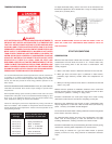
–A drip leg (sediment trap) ahead of the gas control valve to help prevent
dirt and foreign materials from entering the gas control valve.
–A flexible gas connector or a ground joint union between the shutoff
valve and control valve to permit servicing of the unit.
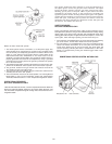
Be sure to check all the gas piping for leaks before lighting the water
heater. Use a soapy water solution, not a match or open flame. Rinse off
soapy solution and wipe dry.
When installed at elevations above 2,000' (610 m), input ratings should be
reduced at the rate of 4 percent for each 1,000' (305 m) above sea level.
WARNING
The appliance and its gas connection must be leak tested before
placing the appliance in operation.
WARNING
The appliance and its individual shutoff valve must be
disconnected from the gas supply piping system during any
pressure testing of that system at test pressures in excess of
1/2 pound per square inch (3.5kPa).
The appliance must be isolated from the gas supply piping system
by closing its individual manual shutoff valve during any pressure
testing of the gas supply piping system at test pressures equal to
or less than 1/2 pound per square inch (3.5kPa).
WARNING
Contaminants in the gas lines may cause improper operation
of the gas control valve that may result in fire or explosion.
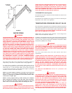
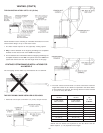
3. 4" or 6" PVC Schedule 40 or CPVC Schedule 40 or 80 piping and
fittings are acceptable materials for the inlet vent system and for
the outlet vent system after the first ten feet. See vent length chart
below.
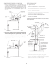
4. It cannot be connected to existing vent piping or chimney.
5. It must terminate vertically to the outdoors.
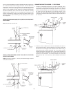
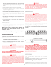
6. The total vertical and horizontal run cannot exceed the
maximum length with number of 90° elbows as specified in
the table below. If more elbows are required, the venting
distance must be reduced 5' (1.5 m) for every 90° elbow:
MODEL MODEL
NUMBER
100-400 100-400
OF
90° DEG.
4" DIA. VENT 6" DIA. VENT
ELBOWS*
MAX. LENGTH MAX. LENGTH
45' (13.7 m) 110' (33.5 m) 1
40' (12 m) 105' (32 m) 2
35' (11 m) 100' (30.5 m) 3
30' (9 m) 95' (29 m) 4
25' (7.6 m) 90' (27.4 m) 5
20' (6 m) 85' (26 m) 6
15' (4.6 m) 80' (24.4 m) 7
10' (3 m) 75' (23 m) 8
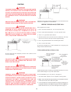
*NOTE: Two 45° elbows are equivalent to one 90° elbow. One 90°
elbow equals 5' (1.5 m) equivalent vent length.
7. Minimum vent length is 18 inches when 4" pipe is used and 45
feet when 6" pipe is used.
NOTE: See page 17 for instructions on cementing PVC or CPVC
pipe and fittings.
GAS PIPING
WARNING
Make sure the gas supplied is the same type listed on the
model rating plate. The inlet gas pressure must not exceed
10.5 in. water column (2.6kPa) for natural gas. The minimum
inlet gas pressure listed on the rating plate is for the purpose
of input adjustment.
WARNING
If the gas control valve is subjected to pressures exceeding
1/2 pound per square inch (3.5kPa), the damage to the