


Installation and Service Manual Upsilon-Series
48
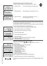
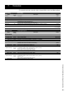
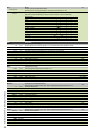
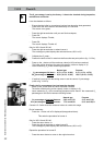
Error Errors
A-B
Error burner A
The last 10 errors with data will be stored.
Choose burner A or B using arrow buttons. Exchanger symbol will show: A or B
Error 01
Select other error number (02-10) with arrow buttons
Every error contains the following info (Press + button for forward, - button for backward)
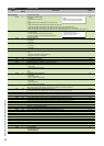
Code Exxscxx
Date
Time
Operational status
T1 flow temperature
T2 return temperature
T1a secondary flow temperature
P1 water pressure
P2 cylinder pump
P3 system pump
P4 cylinder load pump
Damper on/off (no function)
Fan on/off
Gas valve open/closed
Ignition on/off
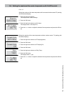
Info Information
Cascade
Information of cascade system
T3 xx.x°C DHW temperature T3 in external cylinder in °C (if connected and P100 is selected for DHW)
T4 xx.x°C Outdoor temperature T4 in °C (if connected)
T10 xx.x°C Temperature T10 sensor in low velocity header in °C
OT sp x.x°C OpenTherm setpoint room temperature in °C (visible when OT is selected)
Req Load xx% Requested load of the cascade system in %
Req Temp xx.x°C Actual requested flow temperature according gradient line of the cascade system in °C
Req Temp xx.x°C End value of the requested flow temperature of the cascade system in °C
Error off Status relay external error signal on-off
P3 off Status system pump P3 on-off
P4 off Status cylinder loading pump P4 on-off
Heatdmnd. off Heat demand
y
es/no on-off
+
‐
Heatdmnd.
off
Heat demand yes/no
on off
LPG / Extra B off Status relay external heating source on-off
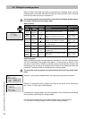
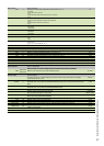
Boiler
Information of the boiler
T1-ave xx.x°C Actual average flow temperature of the boiler in °C
T2-ave xx.x°C Actual average return temperature of the boiler in °C
T3 xx.x°C DHW temperature T3 in external cylinder in °C (if connected and P100 is selected for DHW)
Req Load xx% Requested load of the boiler in %
Req Temp xx.x°C Requester flow temperature of the boiler in °C
3WV closed Status 3-way valve open-closed
P2 off Status DHW pump P2 on-off
P4 off Status cylinder loading pump P4 on-off
BurnerA
Information of burner/heat exchanger A
Select burner A or burner B using + and - button. Symbol heat exchanger will show: A or B
A-B
T1 xx.x°C Actual flow temperature
T1a xx.x°C Actual flow temperature secondary sensor
T2 xx.x°C Actual return temperature
Req Load xx% Requested load in %
Flame x.xx uA Actual ionisation in µA
Water Pr x.xx bar Actual water pressure
FanSpeed xx Actual fan speed in revolutions per minute
Fan PWM x.x% Actual fan capacity in %
Fan off Status fan on-off
Gas off Status gas valve on-off
Ign. off Status ignition on-off
P1 PWM x.x% Actual pump speed in % (only with modulating circulation pump)
P1 off Status pump on-off
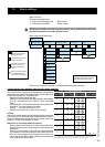
Others
Select burner A or burner B using + and - button. Symbol heat exchanger will show: A or B A-B
Stand-by xx h Number of hours stand by
Burn ON xx h Number of running hours with burner on
Service xx h Number of running hours to go for maintenance interval
Ignition xx Number of times ignition
Faults xx Number of times in error
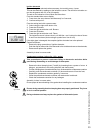
Safety
02017005
S
a
f
e
t
y
02017005
Regul. 01017016
MMI 03017017
OEM par. 00017xxx xxx: 020 = UB70, 080 = UB110, 140 = UB140