


Installation and Service Manual Upsilon-Series
15
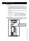
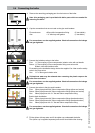
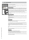
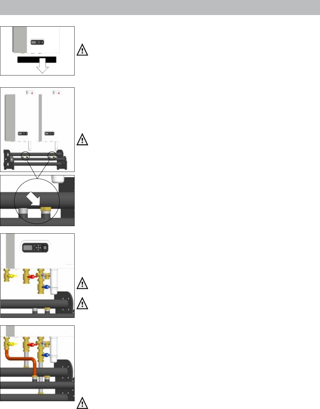
5.4 Connectingtheboiler
A. Remove the remaining packaging part from the bottom of the boiler.
Note:thispackagingpartisprovidedwithboilerpartswhichareneededfor
mountingtheboiler.
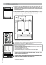
B. Cap the connections that are not used on the pipe work headers:
Flow and return: ø35mm blind compression tting (2 items/boiler)
Gas: 1 ¼" blind cap with gasket (1 item/boiler)
Forconnections,usethesuppliedgaskets.Checkallconnectionsforleakage
andgas-tightness.
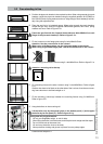
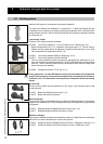
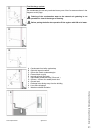
C. Connect the isolations valves to the boiler:
Flow: 1½" at coupling x 35mm compression isolation valve with red handle
Return: 1½" at coupling x 35mm compression tting cross union with
ll/drain valve and isolation valve
Fit according to the installation design choice the supplied 3 or 4 bar overow safety
valve in the cross union.
Gas: 1¼" x 28mm gas isolation valve
Pollutedtestwatermaybereleasedwhenremovingtheplasticcapsonthe
boilerowandreturn.
Forconnections,usethesuppliedgaskets.Checkallconnectionsforleakage
andgas-tightness.
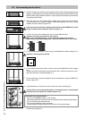
D. Connect the valves to the pipe work headers:
Flow: 35mm pipe pieces with 35mm compression ttings (elbow and socket)
Return: 35mm pipe pieces with 35mm compression ttings (elbow and socket)
Gas: 28mm pipe piece with 1¼" at and 28mm compression tting
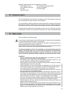
Back-to-back installation:
Flow: 35mm pipe pieces with 35mm compression ttings (bend and socket)
Return: 35mm pipe pieces with 35mm compression ttings (bend and socket)
Gas: 28mm pipe piece with 1¼" at and 28mm compression tting
Forconnections,usethesuppliedgaskets.Checkallconnectionsforleakage
andgas-tightness.
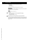
E. Fill the siphon with tap water and t the siphon cup underneath the boiler.
The siphon cup is supplied separately and can be found behind the housing.
Figure 5.4.b
Figure 5.4.c
Figure 5.4.d
Figure 5.4.a