


Installation and Service Manual Upsilon-Series
33
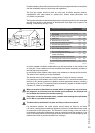
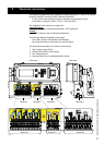
gure 8.f
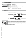
4. Bus communication: 4-pole connector
Position Connection Application PG
Bus communication cable IP67
The 0310289 bus communication cable mutually connects the cascaded boilers by
4-pole connectors on the side of the connection terminals (2 boilers: 1 cable, 3 boilers:
2 cables etc.) and is tted with 2 IP67 tulles. A maximum of 8 boilers can be connected
to the system.
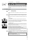
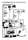
8.1 Externalcontrols
NOTE: -T10mustbeconnected
-T4isadvicedtoconnect.
The Upsilon boiler provides in many possibilities to operate the boilers from external
controls.
Only1typeofcontrolcanbeconnected.Connectionsoftheexternalcontrolmust
bedoneinthemasterboiler(address01)onterminal3andappropriateconnec-
tions.
Below you will nd a description of the possibilities and parameter adjustments to take
account of.
1. On-Offcontact
An On-Off contact is a volt-free switch to create a heat demand with closed contact.
The On-Off control must be connected to terminal 3, position 7 and 8. This is also the
connection for an OpenTherm-control, but it is self-detecting. No specic adjustments
are necessary. See chapter 9.4 to adjust the ow temperature.
2. OpenTherm-control
An OpenTherm-control is a digital controller which is communicating with the boiler ac-
cording the OpenTherm-protocol. The controller calculates continuously the desired ow
water temperature and sends this to the boiler(s).
The OpenTherm-control must be connected to terminal 3, position 7 and 8. This is also
the connection for an On-Off contact, but it is self-detecting.
After connecting an OpenTherm-control P230 will be visible (Setting level, Param. Chap-
ter, Cascade Param.) where the maximum setpoint CH can be adjusted.
For control option 1 and 2 counts that the boiler controls its own output (modulating) to
achieve the desired temperature. When this is achieved the boiler modulates back to
maintain the desired temperature and prevents over shoot.
If an OpenTherm controller is used, it must be ensured that for certain error
messagestheheatdemandisnotomitted.Thiscanresultincompletelossof
heatproduction.
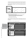
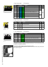
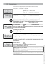
0-10Volt
Open-
Therm
On/Off
T3
DHW
1 2 3 4 5 6 7 8 9 10 11 12 13 14
T10
General
purpose
LWCO
T4
Out
Figure 8.1.a
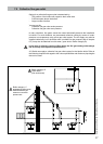
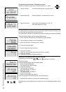
0-10Volt
Open-
Therm
On/Off
T3
DHW
1 2 3 4 5 6 7 8 9 10 11 12 13 14
T10
General
purpose
LWCO
T4
Out
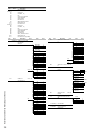
Figure 8.1.b
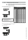
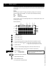
OpenThermerrormessages
ThecodingofthetransmittedErrorMessagesonaOpenThermcontrollerisdisplayedasfollows:
(E)EB(E=ErrorCode=Bandboilernumber)
example:ErrorCodeEx02SC02onboiler6willappearas(0)26