


Installation and Service Manual Upsilon-Series
46
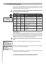
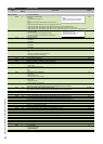
ParamMode Parameterchapter
PARA
factory
setting
Description Range
Cascadeparam.
Cascade parameters
P100 0 Domestic hot water facility 0-8
0: no DHW
1: Solo boiler with 3-wa
y
valve
2: n.a.
3: Solo boiler with c
y
linder loadin
g p
um
p
P4 and 3-wa
y
valve
4: n.a.
5: After low loss header: DHW after LLH with c
y
linder
p
um
p
P2 and P3=of
f
6: After low loss header: DHW after LLH with c
y
linder
p
um
p
P2 and P3=on at heat demand CH
7: After low loss header: DHW loadin
g
s
y
stem after LLH with c
y
linder loadin
g p
um
p
P2, P4 and P3=of
f
8: After low loss header: DHW loadin
g
s
y
stem after LLH with c
y
linder loadin
g p
um
p
P2, P4 and P3=on at heat demand CH
P101 0 Heating 0-3
0: 0÷10V not active
1: 0÷10V= load control (see further P205 until 210)
2: 0÷10V= temperature control (see further P215 until 220)
3: Showroom position
P104 0 Outside sensor T4 0-1
0: autodetect
1: connected
P105 0 Common flow sensor T10
0-1
0: autodetect
1: connected
P106 30 Min. Setpoint T10 0-60
P107 0 Min.Setpoint function T10 0-2
0: off
1: minimum value setpoint at heat demand CH
2: continuously minimum value setpoint
P109 0 Correction outside sensor -5 - 5
P111 20 CH-set gradient-reference 0-60
P112 1,0
CH-set gradient in °C/10sec in steps of 0,1°C
0-10
P114 1 Number of boilers in cascade (To be set manually!)
1-8
P121 1 Relay function Propane/External heating source 0-1
0: Onl
y p
ro
p
ane
1: On/Off external heatin
g
source
P125
1
DHW i it
0 1
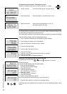
NOTE:
Option 6 and 8 not for Low Temerature
systems, unless separately controlled
ADVICE for using 0-10V:
Choose option 2 for a balanced
behaviour of boiler control.
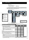
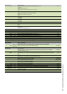
P125 1 DHW priority 0-1
0:No
1: Yes
P157 0 OpenTherm error bit selection 0-2
0: Onl
y
error
s
1: Errors and blockin
g
s
2: Errors, blockin
g
s and messa
g
e
s
P158 0 Error relay selection 0-2
0: Only error
s
1: Errors and blockin
g
s
2: Errors, blockin
g
s and messa
g
e
s
P170 90 Switch on moment relay external heating source 0-100%
When demand is higher then adjusted value the external heating source will be switched on
P171 85 Switch off moment relay external heating source 0-100%
When demand is lower then adjusted value the external heating source will be switched off
P203 2 Overrun time secondary pump P3 in minutes 0-60
At P101 = 1 (Load control):
P205 2
0-10V, load voltage to have minimum heat demand (P208 power) (If P101=1)
0-10
P206 9,5
0-10V, load voltage to have maximum heat demand (P207 power) (If P101=1)
0-10
P207 100%
0-10V, load maximum power (dynamic range) (If P101=1)
0-100
P208 0%
0-10V, load maximum power (dynamic range; 0% is minimum power) (If P101=1)
0-100
P209 1
0-10V, load heat demand when input voltage> (If P101=1)
0-5
P210 0,5
0-10V, load no heat demand when input voltage< (If P101=1)
0-5
At P101 = 2 (Temperature control):
P215 2
0-10V, load voltage to have minimum heat demand (If P101=2)
0-10
P216 9,5
0-10V, load voltage to have maximum heat demand (If P101=2)
0-10
P217 1
0-10V, load heat demand when input voltage> (If P101=2)
0-5
P218 0,5
0-10V, load no heat demand when input voltage< (If P101=2)
0-5
P219 30
0-10V, temperature setpoint at minimum input voltage (If P101=2)
10-90
P220 85
0-10V, temperature setpoint at maximum input voltage (If P101=2)
10-90
P252 2 Slope heating line (K-factor) 0,1 - 9,9
P256 2 Hysteresis Summer/Winter in °C (if T4 was detected) 0-10
P266 2 Switch on delay at heat demand in minutes 0-10
P267 168 Boiler sequence for boilers in cascade in hours 1-255
P283 1 Frost protection 0-1
0: T10 and P3 not active
1: T10 and P3 active
1
:
T10
an
d P3
ac
ti
ve
P284 -5 Switch on temperature frost protection in °C -40 - 20