


OIL BURNER TECHNOLOGY
Omni’s patented burner technology improves the efficiency of the oil burn process by continuous
stabilization of the oil viscosity. Optimum atomization (spray) is accomplished by precisely pre-
heating the oil and air prior to introduction to the combustion chamber. The waste oil enters into
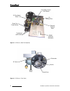
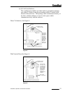
the Oil Pre-Heater Block (figure2) and is pre-heated to operating thermo setpoint, then
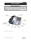
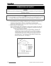
compressed air from the air compressor (figure1) is mixed with the oil prior to spraying out the
nozzle similar to fuel injection, by breaking up the oil droplets into a finer mist or spray
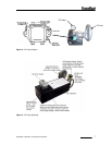
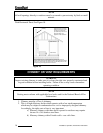
(atomization). Electrodes mounted just above the nozzle (figure3) provides continuous electrical
arc across electrode to electrode igniting the fine oil mist as it sprays out of the nozzle. Once
ignited the flame is forced into a swirl caused by the burners blower and specially designed flame
cone (figure3) providing a very efficient and thorough burn of the waste oil.
Burner Components
• Igniter Transformer: (figure1) Supplies high voltage to the electrodes generating
electrical arc igniting the oil.
• Oil Valve: (figure3) energizes when burner is running and de-energizes when burner is
not running eliminating bleed back of oil out of the Pre-heater block.
• Air Band: (figure1) Adjusts amount of air introduced into the combustion chamber.
• Oil Primary Control: (figure1) Controls the oil burner ignition. Checks for flame in the
combustion chamber, if no flame is detected within 45 seconds, the oil primary will
shutdown the oil burner. To restart the unit, reset the red button on the oil primary.
• Oil Pre-Heater Block: (figure2) Pre-heats the oil and air before entering combustion
chamber.
• Photo Eye: (figure2) Senses flame in combustion chamber and signals oil primary when
no flame is present.
• Igniter Springs: (figure2) Transfers the high voltage from the igniter transformer to the
electrodes (when door is closed)
• Air Pressure Gauge: (figure1) Displays air pressure supplied by onboard air
compressor.
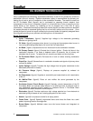
• Air Compressor: (figure1) Supplies air used within pre-heater block to aid in atomization
of the oil.
• Air Muffler/Filter: (figure2) Filters air and muffles the sound generated by the
compressor.
• Pre-Heater Control Circuit Board: (figure2) Precisely controls temperature of the Oil
Pre-Heater Block and controls safety feature of not allowing burner to energize until oil
has established operating thermo setpoint or shutdown burner if Pre-Heater Block
temperature falls below shutdown thermo setpoint.
• Electrodes: (figure3) Provides continuous high voltage electrical arc from electrode to
electrode igniting the waste oil as it is being sprayed out of the nozzle.
• Nozzle: (figure3) Low pressure nozzle for oil spray pattern.
• Flame Cone: (figure3) Specially engineered flame cone forces the flame into a swirl
pattern improving the burn thoroughness.
• Burner Motor: (figure3) Multitask motor turns the burner blower and integrated air
compressor.
8
Installation, Operation, And Service Instructions