


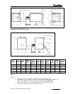
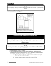
Baro
m
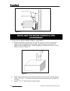
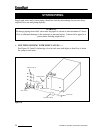
etric Draft Control
Pitch U
p
1/4”
p
er foo
t
18”
Strai
g
ht Run Preferred
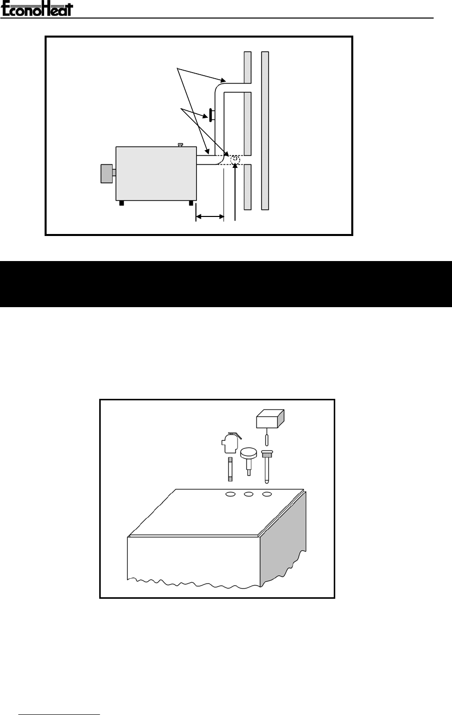
Figure 12.
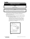
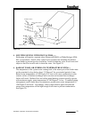
INSTALLING THE BOILER CONTROLS AND
ACCESSORIES
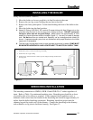
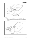
1. Accessories for Boilers OWB-9, OWB-15, and OWB-25:
a) Take the L8148A Aquastat relay, the well, the pressure relief valve with pipe
nipple and the temperature/pressure gauge from the large carton which was
packed in the wirebound crate. Install in tappings provided at the top rear of the
boiler as shown in Figure 13.
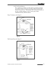
Figure 13.
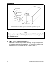
b) Take the boiler drain from the same carton and connect it to the 3/4 inch opening
of the 1 1/4 x 3/4 x 1 1/4 inch tee in the boiler return manifold at the bottom rear
of boiler.
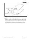
c) Install 1 1/4 x 3” Nipple and Circulator Flange.
20
Installation, Operation, And Service Instructions