


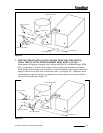
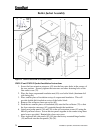
5. Attach one door bracket (18) to the bottom of both the left and right side jacket
panels. Use two 8-32x1/2” screws (19) and nuts (20) to assemble each door
bracket.
6. Attach the left and right side jacket panels to the boiler. The front end of the right
side panel is attached to the hinge using 10-24x3/4 screws (21). The front end of
the left side panel is also attached to the front jacket mounting bracket (23) using
10-24x3/4 screws. The rear of both the left and right panels are attached to the
rear panel using #10x1/2 sheet metal screws.
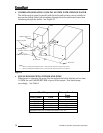
7. Install a #10x1/2 sheet metal screw into the remaining hole in the rear of the right
side jacket panel which secures the rear of the wireway.
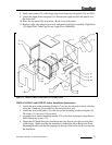
8. Attach the top jacket panel (5) using four #10x1/2 sheet metal screws.
9. Attach the flue collector cover (4) using four #10x 1/2 sheet metal screws.
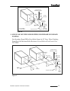
10. Press the door switch (16) into the door switch bracket (17). Connect the door
switch leads to the switch (it does not matter which wire is connected to which
side of the switch). Attach the door switch bracket to the right side jacket panel
using a 10-24x3/4 machine screw (21).
11. Mount the door knobs (25) to the front panel (24) using two 8-32x1/4 screws (26).
12. Mount the front jacket panel on the boiler.
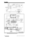
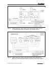
13. Connect the loose end of the 6” conduit assembly to the limit control. Connect
the black wire to terminal “B1” and the white wire to terminal “B2”.
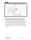
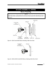
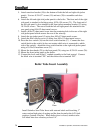
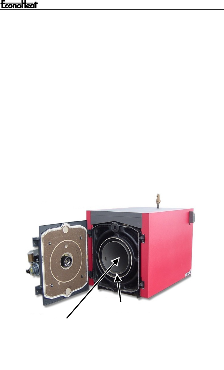
Boiler Tube Insert Assembly
Dam
Install Stainless Steel Tube Insert with external stitch weld touching 1
s
t
water section high point of casting and the dam located at the 6 O’clock
p
osition. (bottom of boiler). When boiler door is closed, stainless tube
will inbed into door refractory at least 1/4”.
36
Installation, Operation, And Service Instructions