


Single Zone Wiring
WARNING
All wiring and grounding must be done in accordance with the authority having
j
urisdiction or, in the absence of such authority, with the National Electrical Code
(
ANSI/NFPA70
)
.
1)
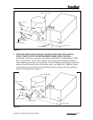
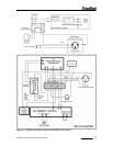
120 Volt Wiring—The boiler should be provided with its own 20A branch circuit
with fused disconnect. All 120 volt connections are made inside the L8148A aquastat
relay as follows (also see Fig. 31 or 32):
• Hot (“black”)- Terminal “L1”
• Neutral (“white”)- Terminal “L2”
• Ground (“Green” or bare)- Ground screw on case of L8148A
2)
Thermostat Wiring—Follow thermostat manufacturer instructions. To insure proper
thermostat operation, avoid installation in areas of poor air circulation, hot spots (near
any heat source or in direct sunlight), cold spots (outside walls, walls adjacent to
unheated areas, locations subject to drafts). Provide Class II circuit between
thermostat and boiler. Connect thermostat wire leads to terminals “T” and “T” inside
L8148A aquastat relay.
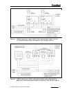
Wiring Variations
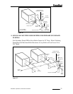
1)
Multiple Circulator Zones—Figure 35 shows wiring for two or more circulator zones
using Honeywell R845As. One R845A is required for each circulator zone.
Circulator terminals “C1” and “C2” on the L8148A are not used. A DPST
Honeywell RA832A may be substituted in place of the R845A using the “X” and “X”
terminals in place of the “5” and “6” terminals on a R845A. A call for heat from any
thermostat will energize the DPST relay in that zone”s R845A. When this relay is
energized, electrical continuity is created between terminals 3 and 4, energizing the
circulator for that zone. At the same time, electrical continuity is created between
terminals 5 and 6 on the R845A, creating a current path from terminal “T” to “T” on
the L8148A. Assuming that the supply water temperature is below the high limit
setting, the normal ignition sequence will be initiated.
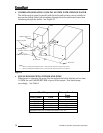
2)
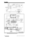
Multiple Zones using Zone Valves—Figure 34 shows wiring for multiple zones using
Honeywell V8043F zone valves. This wiring diagram may be used for other 24-volt
zone valves as long as they are equipped with end switches.
Do not attempt to use the
transformer on the L8148A to power the zone valves; use a separate transformer. Up
to five V8043Fs may be powered by one 48VA transformer, such as the Honeywell
AT87A. A call for heat from a given thermostat will result in the application of 24
volts across the TH and TR terminals on the corresponding zone valve, energizing the
zone valve motor. The zone valve opens and the end switch contacts are then made.
The end switches are connected in parallel with each other and to the “T” and “T”
Installation, Operation, And Service Instructions 37