


18
Never use this water heater unless it is completely full of water. To prevent
damagetothetank,thetankmustbelledwithwater.Watermustow
fromthehotwaterfaucetbeforeturning“ON”gastothewaterheater.
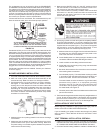
Tollthewaterheaterwithwater:
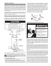
1. Close the water heater drain valve by turning handle to the right
(clockwise).Thedrainvalveisonthelowerfrontofwaterheater.
2. Open the cold water supply valve to the water heater.
NOTE: The cold water supply valve must be left open when the
water heater is in use.
3. Toinsurecompletellingofthetank,allowairtoexitbyopeningnearest
hotwaterfaucet.Allowwatertorununtilaconstantowisobtained.
This will let air out of the water heater and the piping.
4. Check all water piping and connections for leaks. Repair as needed.
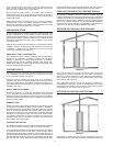
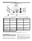
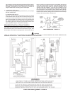
VENT PIPE ASSEMBLY
There are three parts of the vent pipe assembly that connect the water
heaterexhaust(locatedonlowerbacksideofwaterheater)toinletofthe
blowerassembly(mountedontopofwaterheater)asshowninFigure
1. These parts will need to be assembled according to the instructions
in the VENT PIPE PREPARATION section of this manual. These PVC
parts should be assembled with ASTM D-2564 grade cement.
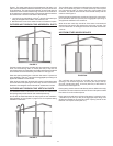
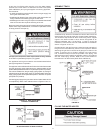
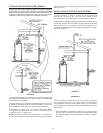
AssembleVentPipeAssemblies#1,#2and#3(SeeFigure1)prior
to cementing. The preferred orientation of Vent Pipe Assembly #1
(CondensateU-Assembly)isshowninFigure16.Howeverthis
assembly may be rotated to a different orientation as needed for the
specicinstallationrequirements.Notetherotationalorientationof
each part by marking a line several inches long across the joints.The
long tube of Vent Pipe Assembly #2 should be approximately
vertical. If it is found that either of the two pieces of pipe in Vent
PipeAssembly#2aretoolongforpropert-up,thenremoveas
littlematerialaspossibletoimprovethet-up.Keepinmindthat
the pipes will insert slightly further into the elbows when cement
is applied as it acts as a lubricating agent. The vertical distance
fromthebottomoftheCondensateU-Assemblytotheoorthat
supportsthewaterheatershouldbeapproximately0.25”(0.64cm),
see Figure 16. Disassemble the parts and cement back together
using the alignment marks. After the cement dries, attach the
assembly to the blower and the water heater exhaust using the
supplied rubber boots and hose clamps.
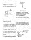
A condensate trap is incorporated in the bottom of this vent pipe assembly.
See the CONDENSATE section of this manual for further details.
VENTING