


20
PLANNING THE VENT SYSTEM
Plan the route of the vent system from the discharge of the blower
to the planned location of the vent terminal. Refer to VAA instruction
on page 26 while planning the vent system.
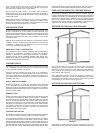
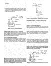
1. Layout total vent system to use a minimum of vent pipe and elbows.
2. Thiswaterheateriscapableofventinguegasesequivalentto
25’(7.6m)of2”pipe,65’(19.8m)of3”pipe,or128’(39.0m)of
4”pipeaslistedinTable2.
TABLE 2.
Number of 2” Maximum 3” Maximum 4” Maximum
90° Elbows Pipe - ft. (m) Pipe - ft. (m) Pipe - ft. (m)
1 20(6.1) 60(18.3) 120(36.6)
2 15(4.6) 55(16.8) 112(34.1)
3 10(3.0) 50(15.2) 104(31.7)
4 -- 45(13.7) 96(29.3)
5 -- 40(12.2) 88(26.8)
6 -- 35(10.7) 80(24.3)
Theminimumventlengthsforeachofthepipesizesisone90°ontopof
theunitplus2’(61cm)ofstraightpipeandtheappropriatetermination.
NOTE:Theequivalentfeet(m)ofpipelistedaboveareexclusive
of the termination. That is, the termination, with an installed
screen, is assumed to be in the system and the remainder of the
system must not exceed the lengths discussed above.
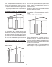
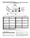
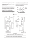
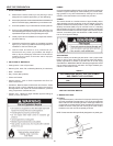
3. The blower discharge adapter is made to accept only straight
sectionsof2”pipe.Tostart,aminimumof2inches(5.1cm)of2”
pipe must be attached to the blower discharge, see Figure 17.
If using 2” inch vent pipe:
Aminimumof2inches(5.1cm)mustbeattachedtotheblower
beforetherstelbow.Aftertherstelbowaddtheadditional
venting required for the installation. The total system cannot
exceed the lengths discussed above, where each elbow is equal
to5feet(1.5m)ofstraightpipe.
If using 3” or 4” inch vent pipe:
Twoinches(5.1cm)ofpipemustbeattachedtoblowerdischargebefore
adding a reducer to acquire desired pipe diameter. An appropriately
sized45degreeschedule40DWVelbow(eldsupplied)ventterminal
mustbeobtainedwithanequivalentscreen(suppliedinventkit).
The total system cannot exceed equivalent pipe lengths discussed
abovewhereeachelbowisequalto5feet(1.5m)ofstraightpipe
(3”ventpipe)or8feet(2.4m)ofstraightpipe(4”ventpipe).
NOTE: ThisunitcanbeventedwithPVCpipematerials(CellularCore
ASTM-F891; DWV ASTM-D2665 or CSA B181.2; Schedule 40, 80, 120
ASTM-D1785 or CSA B137.3; or SDR Series ASTM-D2241 or CSA
B137.3),CPVCpipematerials(CPVC41ASTM-D2846orCSAB137.6;
Schedule40,80ASTM-F441orCSAB137.6;orSDRSeriesASTM-F442),
ABSpipematerials(Schedule40DWVASTM-D2661orCSAB181.1
orSchedule40DWVCellularCoreASTM-F628).Fittings,otherthan
TERMINATIONshouldbeequivalenttoPVC-DWVttingsmeeting
ASTMD-2665(UseCPVCttings,ASTMF-438forCPVCpipeand
ABSttings,ASTMD-2661/3311forABSpipe).IfCPVCorABSpipe
andttingsareused,thenpropercementmustbeusedforalljoints,
includingjoiningpipetoTermination(PVCMaterial).Iflocalcodesdonot
allow use of PVC termination when a material other than PVC is used
forventing,thenanequivalentttingofthatmaterialmaybesubstituted
ifscreeninPVCterminalisremovedandinsertedintonewtting.
PVC Materials should use ASTM D-2564 Grade Cement; CPVC
Materials should use ASTM F-493 Grade Cement and ABS Materials
should use ASTM D-2235 Grade Cement.
If water heater is being installed as a replacement for an existing power
vented heater in pre-existing venting, a thorough inspection of existing
venting system must be performed prior to any installation work. Verify
that correct material as detailed above has been used, and that minimum
or maximum vent lengths and terminal location as detailed in this manual
have been met. Carefully inspect entire venting system for any signs
of cracks or fractures, particularly at joints between elbows and other
ttingsandstraightrunsofventpipe.Checksystemforsignsofsagging
or other stresses in joints as a result of misalignment of any components
in system. If any of these conditions are found, they must be corrected in
accordance with venting instructions in this manual before completing
installation and putting water heater into service.
NOTE: A. For water heaters in locations with high ambient
temperatures(above100°F)itisrecommendedthatCPVCorABS
pipeandttingsbeused.B.A22.5degreeelbow(2”ventpipe)ora
45degreeelbow(3”and4”ventpipe)withaninstalledscreenVENT
TERMINAL must be used in all cases.
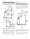
4. There will be some installations where condensate will be formed
in the horizontal runs of the vent system. This condensate will
run into the condensate boot attached to the blower and out the
tting.Thewaterheaterisshippedwithcondensatehosethat
attachestothettingonthecondensateboot.NootherTeeor
ttingisrequired.SeeFigures17,20and21.
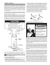
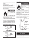
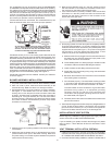
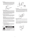
CONDENSATE
This water heater is a condensing unit and requires a drain to be
located in close proximity to allow condensate to drain safely. One hose
fromblowerhousing,twoexiblehosesfrombloweroutletadaptor,
alongwithanotherexiblehosefromVAAifinstalled,runtobarbttings
onventpipeassembly#2.Hoseisclampedbyrubberclipsandexible
hoses by a clamp on jacket top cover. See Figure 17. Condensate
drains from the unit at the exhaust tee located at the bottom of the unit
(seegure16).Condensatefromthiswaterheaterismildlyacidic.
Please note that some local codes require that condensate is treated
byusingapHneutralizinglterpriortodisposal.
NOTE:Itisimportantthattheeldsupplieddrainlinesbeyondthe1/2”
adaptor of vent pipe assembly #1 should be installed continuously
tilted downward toward an appropriate drain. See Figure 16. If these
instructions are not followed or if condensate drain line is blocked, water
will spill from condensate trap. Do not block the holes in the hex plug on
top of a small tee in vent pipe assembly #1. As with every water heater
installation, a drain pan should be used to prevent water damage to
surrounding area. If necessary, a condensate pump with an incorporated
reservoir may be used to pump water to an appropriate drain. To avoid
condensatespillage,selectapumpwithanoverowswitch.
Caution must be used to ensure that drain is free and clear of debris
and will not allow backflow through the condensate drain line.
Consideration must be given to avoid freezing of the condensate lines
which could result in excessive build up of condensate inside the water
heater. Waterproof heat tape may be required to prevent freezing of
condensate lines. Please ensure that the outlet of condensate drain
does not create a slippery condition which could lead to personal
injury. Care should be taken to ensure there is no kink or twist in any
condensatehose.IfaVAAisnotinstalled,theunusedbarbttingin
vent pipe assembly #2 should be plugged using one of the break-
away plugs.
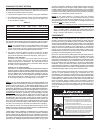
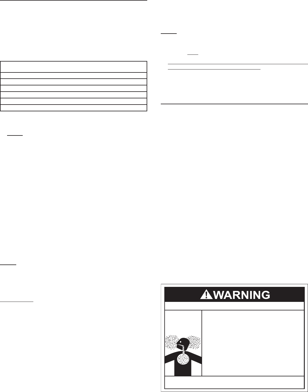
Breathing Hazard - Carbon Monoxide Gas
•
Do NOT block the holes in the hex plug of vent pipe
assembly #1.
•
Do NOT elevate any portion of the field supplied drain
line beyond the 1/2" adaptor above the adaptor. This
must be true for entire length of the drain line including
the exit into an appropriate drain
.
•
Condensate lines must be free and clear of debris and
must not allow back flow through drain line. Condensate
lines must be able to flow freely to an appropriate drain.
•
Do not allow condensate lines to become crimped closed.
•
Analyze entire vent system to make sure that condensate
will not become trapped in a section of vent pipe and
therefore reduce open cross sectional area of vent.
Breathing carbon monoxide can cause brain damage or death.
Always read and understand instruction manual.