


24
VENT ATTENUATION ASSEMBLY
INSTALLATION INSTRUCTIONS
TheVentAttenuationAssembly(VAA)isdesignedtoprovidea
reduction in fan noise created in the blower wheel. This installation
of this VAA is optional. Review directions thoroughly prior to installing
the new VAA. Please contact the manufacturer of the water heater as
shown in the instruction manual with any questions or for additional
product support.
VENT ATTENUATION ASSEMBLY KIT PARTS LIST
The kit consists of the following items. If a part is missing, use the
contact information in the instruction manual to acquire missing
component(s).
•ventattenuationassembly
•exibletubing
•instructionsheet
VENT ATTENUATION ASSEMBLY INSTALLATION
The VAA is designed for both vertical and horizontal installations.
The vertical installation and horizontal installations will require that
theexiblecondensatehosetobeattachedtothecondensatehose
barb located on the bottom of the VAA to release condensate. See
instructions and diagrams that follow for a more detailed description.
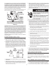
Breathing Hazard - Carbon Monoxide Gas
•
Do NOT block the holes in the hex plug of vent pipe
assembly #1.
•
Do NOT elevate any portion of the field supplied drain
line beyond the 1/2" adaptor above the adaptor. This
must be true for entire length of the drain line including
the exit into an appropriate drain
.
•
Condensate lines must be free and clear of debris and
must not allow back flow through drain line. Condensate
lines must be able to flow freely to an appropriate drain.
•
Do not allow condensate lines to become crimped closed.
•
Analyze entire vent system to make sure that condensate
will not become trapped in a section of vent pipe and
therefore reduce open cross sectional area of vent.
Breathing carbon monoxide can cause brain damage or death.
Always read and understand instruction manual.
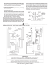
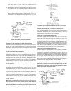
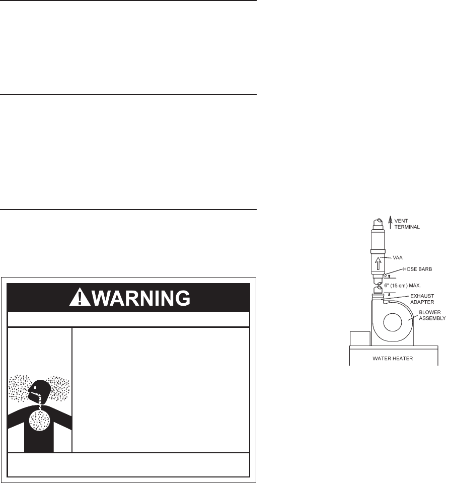
Vertical VAA Installations (Recommended)
1. The VAA is designed to accept two inch PVC pipe into
the adapters on both ends. The VAA must be installed with the
condensate hose barb pointing downward. See Figure 22. The
VAAhasanembossedowarrowtoreectproperorientation.
For optimum performance, install VAA as close as possible to
the blower assembly.
2. UsestandardPVCcement(notincludedwithkit)andgluethetwo
inch PVC pipe coming from the blower into the VAA.
3. Perform the same sequence on the PVC pipe coming from the
exhaustside(ventterminalside)oftheVAA.
4. Make sure the VAA and vent pipe is supported securely to
apermanentfixture(studorwall).Usestandardsupport
straps(notsuppliedwithkit)thatmaybefoundatalocal
hardware store. Failure to properly support the VAA and the
surrounding vent pipe could create a hazardous situation. DO
NOT puncture any surface of the VAA.
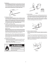
5. Locate flexible tubing. Slide one end of tubing over the hose
barb located near end of the VAA. The ridges on the hose
barb should prevent the tubing from sliding off, however,
to ensure there are no leaks and possible dislocation from
hosebarb,useawiretieorhoseclamp(notsuppliedwithkit)
and secure.
6. Take the other end of the flexible tubing and slide it through
the hose clamp on the jacket top cover and install it into one
of the four barb fittings in vent pipe assembly #2.
7. Once installed along with the rest of the vent configuration,
make sure to operate the unit through at least one heat up
cycle to ensure there is no leakage around the hose barb or
any joints of the VAA or vent pipe system.
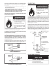
FIGURE 22: Typical Vertical Installation
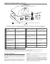
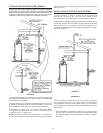
Horizontal VAA Installations
1. The VAA is designed to accept two inch PVC pipe into the
adapters on both ends. The VAA must be installed with the
condensate hose barb pointing downward. See Figure 23. The
VAA has an embossed flow arrow to reflect proper orientation.
For optimum performance, install VAA as close as possible
to the blower assembly.
2. UsestandardPVCcement(notincludedwithkit)andgluethe
two inch PVC pipe coming from the blower into the VAA.
3. Perform the same sequence on the PVC pipe coming from the
exhaustside(ventterminalside)oftheVAA.
4. Make sure the VAA and vent pipe is supported securely to a
permanentxture(studorwall).Usestandardsupportstraps
(notsuppliedwithkit)thatmaybefoundatalocalhardware
store. Failure to properly support the VAA and the surrounding
vent pipe could create a hazardous situation. DO NOT puncture
any surface of theVAA.
5. Locate flexible tubing. Slide one end of tube over the hose
barb located near end of the VAA. The ridges on the hose
barb should prevent the tube from sliding off, however, to
ensure there are no leaks and possible dislocation from hose