


15
DISCONNECT THE APPLIANCE AND ITS MANUAL GAS SHUTOFF
VALVE FROM THE GAS SUPPLY PIPING SYSTEM DURING ANY
SUPPLY PRESSURE TESTING EXCEEDING 1/2 PSIG (3.45Kpa). GAS
SUPPLY LINE MUST BE CAPPED WHEN DISCONNECTED FROM THE
HEATER. FOR TEST PRESSURES OF 1/2 PSIG (3.45Kpa) OR LESS, THE
APPLIANCE NEED NOT BE DISCONNECTED, BUT MUST BE ISOLATED
FROM THE SUPPLY PRESSURE TEST BY CLOSING THE MANUAL GAS
SHUTOFF VALVE.
BEFORE PLACING THE HEATER IN OPERATION, CHECK FOR GAS
LEAKAGE. USE SOAP AND WATER SOLUTION OR OTHER MATERIAL
ACCEPTABLE FOR THE PURPOSE OF LOCATING GAS LEAKS. DO NOT
USE MATCHES, CANDLES, FLAME OR OTHER SOURCES OF IGNITION
FOR THIS PURPOSE.
PURGING
Gas line purging is required with new piping or systems in which air has
entered.
CAUTION
PURGING SHOULD BE PERFORMED BY PERSONS EXPERIENCED IN
THIS TYPE OF GAS SERVICE. TO AVOID RISK OF FIRE OR EXPLOSION,
PURGE DISCHARGE MUST NOT ENTER CONFINED AREAS OR
SPACES WHERE IGNITION CAN OCCUR. THE AREA MUST BE WELL
VENTILATED AND ALL SOURCES OF IGNITION MUST BE INACTIVATED
OR REMOVED.
GAS METER SIZE - CITY GASES ONLY
Be sure that the gas meter has sufcient capacity to supply the full rated gas
input of the water heater as well as the requirements of all other gas red
equipment supplied by the meter. If the gas meter is too small, ask the gas
company to install a larger meter having adequate capacity.
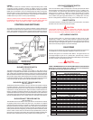
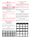
GAS PRESSURE REGULATION
Main line gas pressure to the water heater should be between a maximum
10.5" (2.59Kpa) W.C. (14.0"/3.45Kpa for propane) and a minimum as shown
in Table 4: that is, for Natural Gas, 4.8" (1.18Kpa) W.C. and 8.5" (2.08Kpa) for
Propane Gas. The inlet gas pressure must not exceed the maximum value.
A service regulator must be installed within 10' (305 cm) of unit.
WARNING
FAILURE TO INSTALL A PRESSURE REGULATOR WITHIN 10 FEET OF
THE WATER HEATER CAN RESULT IN LEAKAGE OF FLUE GASES INTO
THE SURROUNDING ROOM. SERIOUS PERSONAL INJURY OR DEATH
COULD RESULT FROM INHALATION OF CARBON MONOXIDE GAS.
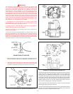
GAS VALVES
WARNING
SHOULD OVERHEATING OCCUR OR THE GAS SUPPLY FAIL TO
SHUT OFF, TURN OFF THE MANUAL GAS CONTROL VALVE TO THE
APPLIANCE.
SYSTEM CONNECTIONS
The system installation must conform to these instructions and to the local
code authority having jurisdiction. Good practice requires that all heavy
piping be supported.
THERMOMETERS (Not Supplied)
Thermometers should be obtained and eld installed as shown in the
installation diagrams.
Thermometers are installed in the system as a means of detecting the
temperature of the outlet water supply.
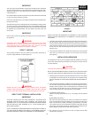
RELIEF VALVE
This heater is equipped with an approved temperature and pressure relief
valve. ASME ratings cover pressure relief. CSA ratings cover release rate
with temperature actuation.
FOR SAFE OPERATION OF THE WATER HEATER, THE RELIEF VALVE(S)
MUST NOT BE REMOVED OR PLUGGED.
In addition to the appliance relief valve, each remote storage tank
which may be used in conjunction with this appliance shall also be
installed with a properly sized, rated and approved temperature (ANSI)
and pressure (ASME) relief valve(s). This relief valve shall comply
with the standard for relief valves for hot water supply systems. ANSI
Z21.22-CSA 4.4.
Your local code authority may have other specific relief valve
requirements.
WARNING
THE PURPOSE OF A RELIEF VALVE IS TO AVOID EXCESSIVE
PRESSURE OR TEMPERATURE INTO THE STEAM RANGE, WHICH
MAY CAUSE SCALDING AT FIXTURES, TANK EXPLOSION, SYSTEM
OR HEATER DAMAGE. NO VALVE IS TO BE PLACED BETWEEN THE
RELIEF VALVE AND THE TANK.
A DRAIN LINE MUST BE CONNECTED TO THE RELIEF VALVE TO
DIRECT DISCHARGE TO A SAFE LOCATION TO AVOID SCALDING OR
WATER DAMAGE. THIS LINE MUST NOT BE REDUCED FROM THE
SIZE OF THE VALVE OUTLET AND MUST NOT CONTAIN VALVES OR
RESTRICTIONS, NOR SHOULD IT BE LOCATED IN FREEZING AREAS.
DO NOT THREAD OR CAP THE END OF THIS LINE. RESTRICTED OR
BLOCKED DISCHARGE WILL DEFEAT THE PURPOSE OF THE VALVE
AND IS UNSAFE. THE DISCHARGE LINE SHALL BE INSTALLED TO
ALLOW COMPLETE DRAINAGE OF BOTH THE VALVE AND LINE.
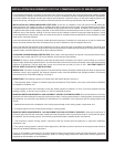
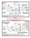
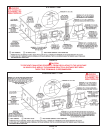
WATER LINE CONNECTIONS
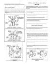
This manual provides detailed installation diagrams (see back section of this
manual) for typical methods of application for the water heaters.
The water heater may be installed by itself, or with a separate storage
tank.
CLOSED SYSTEM
CAUTION
A closed system will exist if a check valve (without bypass), pressure reducing
valve (without bypass), or a water meter (without bypass) is installed in the
cold water line between the water heater and street main (or well).
Excessive pressure may develop causing premature tank failure or
intermittent relief valve operation. This type of failure is not covered
by the limited warranty. An expansion tank or a similar device may be
required in the inlet supply line between the appliance and the meter or
valve to compensate for the thermal expansion of water under supply
pressure.
If a water heater is installed in a closed water system, check local codes
or contact the water supplier or local plumbing inspector on how to control
this situation.
WATER (POTABLE) HEATING AND SPACE HEATING
1. All piping components connected to this unit for space heating
applications shall be suitable for use with potable water.
2. Toxic chemicals, such as those used for boiler treatment, shall
NEVER be introduced into this system.