


13
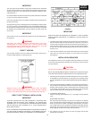
LOW GAS PRESSURE SWITCH
(SEE FIGURE 12)
The Low Gas Switch (LGS) is a single-pole, normally open pressure switch
that will close its contacts when a rising pressure of 5.0 in. (1.25Kpa) W.C.
is encountered. The contacts will open when the pressure falls below the
xed set point of 4.8"WC (1.18Kpa) for natural gas models and 8.5"WC
(2.08Kpa) for propane models. The LGS monitors the gas supply pressure
to the heater. If the gas supply falls below 5.0 in. (1.25Kpa) W.C., the main
burner is extinguished (if heater is running) or the heater will not start up.
ON/OFF SWITCH
The ON/OFF Switch is a single-pole, single-throw rocker switch. This switch
provides 120V from the line source to the heater.
CAUTION
THE WATER HEATER IS POLARITY SENSITIVE. BEFORE APPLYING
ELECTRICITY TO THIS HEATER BE CERTAIN THAT SUPPLY NEUTRAL
WIRE TO GROUND CHECK INDICATES ZERO VOLTAGE.
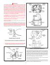
HOT SURFACE IGNITER
The Hot Surface Igniter is a device that ignites the main burner by high
temperature (>1800°F or >982°C). When 120VAC is applied to the igniter,
sufcient heat is generated to ignite the main burner. Although improvements
have been made to strengthen the igniter, it is still fragile and care must be
taken when handling the igniter to prevent breakage.
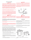
GAS PIPING
Contact your local gas service company to ensure that adequate gas service
is available and to review applicable installation codes for your area.
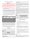
Size the main gas line in accordance with Table 3. The gures shown are
for straight lengths of pipe at 0.5" (125Pa) W.C. pressure drop, which is
considered normal for low pressure systems Note that ttings such as elbows
and tees will add to the pipe pressure drop.
CAUTION
DO NOT USE FLEXIBLE GAS PIPING.
TABLE 3. MAXIMUM CAPACITY OF PIPE IN CUBIC FEET OF GAS PER HOUR
(Based upon a Pressure Drop of 0.5") Water Column and 0.6 Specic
Gravity Gas and max. gas pressure of 0.5 psig)
CEMENT
The cement should be a bodied cement of approximately 500 to 1600
centipoise viscosity containing 10-20% (by weight) virgin PVC material
solvated with tetrahydrofuran (THF). Small quantities of dimethyl formamide
(DMF) may be included to act as a retarding agent to extend curing time.
Select the proper cement; Schedule 40 cement should be used for Schedule
40 pipe. Never use all-purpose cements, commercial glues and adhesives
or ABS cement to join PVC or CPVC pipe and ttings.
SAFETY PRECAUTION: PRIMERS AND CEMENTS ARE EXTREMELY
FLAMMABLE AND MUST NOT BE STORED OR USED NEAR HEAT OR
OPEN FLAME. ALSO, USE ONLY IN A WELL-VENTILATED AREA.
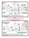
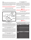
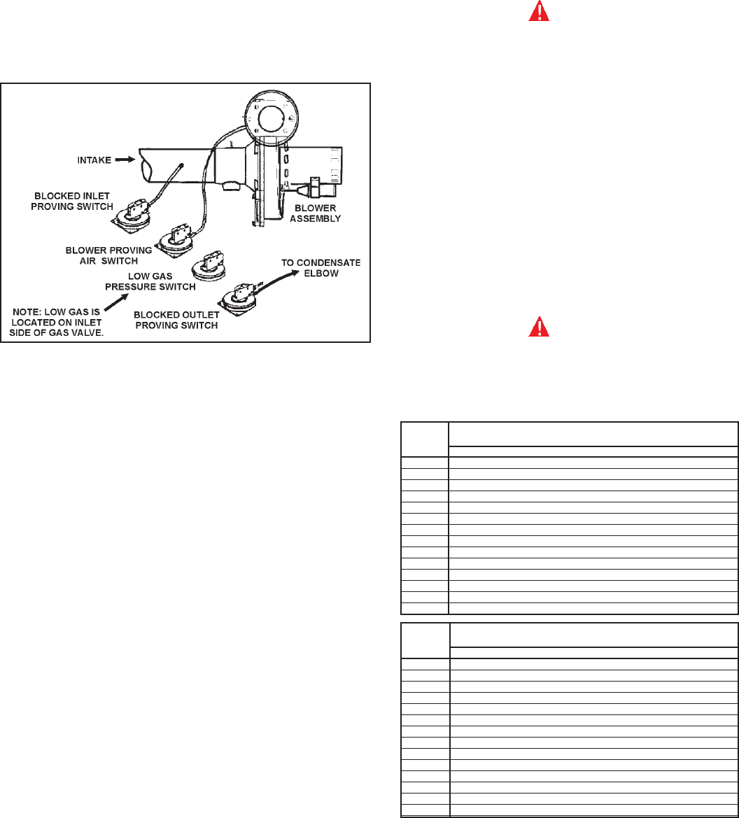
CONTROLS AND SWITCHES
All models are provided with four pressure switches. These switches are
essential to the safe and proper operation of the unit. All switches are wired in
series. The controller is set up to shut the unit down whenever there is a failure of
any of the switches. It is important to understand the purpose of each switch.
FIGURE 12.
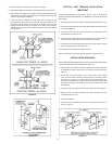
BLOWER PROVER SWITCH
(SEE FIGURE 12)
The Blower Prover Switch is provided on the heater to verify that the fan is
operating. It is a positive pressure switch whose electrical contacts are normally
open. When the fan increases the pressure in the burner, the pressure switch will
allow the electrical contacts to close. The pressure switch is connected to the burner
tap by a piece of tygon tubing. This tubing must be connected in order for the switch
to change the electrical contacts. The controller requires that the electrical contacts
on this air ow switch be open before it will allow the blower to come on.
BLOCKED OUTLET PROVER SWITCH
(SEE FIGURE 12)
The Blocked Outlet Prover Switch is set up to shut the unit off when a build-up
of positive pressure in the exhaust vent pipe occurs. This switch is a positive
pressure switch that requires an increase in pressure to change the electrical
contacts from normally closed to open. When this switch prevents the unit from
igniting, most likely the exhaust is blocked by some means Check to see if the
condensate is allowed to ow freely from the exhaust elbow and for obstructions
in the exhaust venting and exhaust vent terminal. Also verify that there is no more
than fty equivalent feet (15.2 m) of three inch PVC vent pipe on the exhaust.
BLOCKED INLET PROVER SWITCH
(SEE FIGURE 12)
The Blocked Inlet Prover Switch is set up to shut the unit off when a build-up
of negative pressure in the intake vent pipe occurs. This switch is a negative
pressure switch that requires an increase in negative pressure to change the
electrical contacts from normally closed to open. The switch is connected to the
pressure tap on the PVC ange connected to the inlet of the blower. When this
switch prevents the unit from igniting, most likely the intake is blocked by some
means. Check to see if there is no more than fty equivalent feet (15.2 m) of
three inch PVC vent pipe on the intake. Also verify that the intake and intake vent
terminal is free of obstructions that may prevent air from entering the unit.
LENGTH NORMAL IRON PIPE SIZES (INCHES)
IN INPUT IN THOUSANDS BTU/HR
FEET 1/2" 3/4" 1" 1 1/4" 1 1/2" 2" 2 1/2" 3" 4"
10 175 360 680 1400 2100 3960 6300 11000 23000
20 120 250 485 950 1460 2750 4360 7700 15800
30 97 200 375 770 1180 2200 3520 6250 12800
40 82 170 320 660 990 1900 3000 5300 10900
50 73 151 285 580 900 1680 2650 4750 9700
60 66 138 260 530 810 1520 2400 4300 8800
70 61 125 240 490 750 1400 2250 3900 8100
80 57 118 220 460 690 1300 2050 3700 7500
90 53 110 205 430 650 1220 1950 3450 7200
100 50 103 195 400 620 1150 1850 3250 6700
125 44 93 175 360 550 1020 1650 2950 6000
150 40 84 160 325 500 950 1500 2650 5500
175 37 77 145 300 460 850 1370 2450 5000
200 35 72 135 280 430 800 1280 2280 4600
LENGTH NORMAL IRON PIPE SIZES (INCHES)
IN INPUT IN KW
METERS 1/2" 3/4" 1" 1 1/4" 1 1/2" 2" 2 1/2" 3" 4"
3.0 51 105 199 410 615 1160 1845 3221 6735
6.1 35 73 142 278 428 805 1277 2255 4626
9.1 28 59 110 225 346 644 1031 1830 3748
12.2 24 50 94 193 290 556 878 1552 3192
15.2 21 44 83 170 264 492 776 1391 2840
18.3 19 40 76 155 237 445 703 1259 2577
21.3 18 37 70 143 220 410 659 1142 2372
24.4 17 35 64 135 202 381 600 1083 2196
27.4 16 32 60 126 190 357 571 1010 2108
30.5 15 30 57 117 182 337 542 952 1962
38.1 13 27 51 105 161 299 483 864 1757
45.7 12 25 47 95 146 278 439 776 1610
53.3 11 23 42 88 135 249 401 717 1464
61.0 10 21 40 82 126 234 375 688 1347