


21
5. Check the vent system seams and joints and ensure that there is no
discharge of ue products into the room.
6. Check the input rate.
For appliance installation locations with elevations above 6500 feet
(1982 meters) refer to HIGH ALTITUDE INSTALLATIONS section of this
manual.
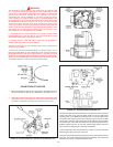
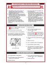
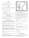
a. Attach a pressure gauge (manometer) to the manifold pressure tap
(Figure 16) and refer to Table 4, page 20 for correct pressure.
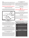
b. Use this formula to “clock” the meter. Be sure other gas consuming
appliances are not operating during this interval.
3600
X H = Btuh
T
Should it be necessary to adjust the gas pressure to the burner, to obtain
the full input rate, the steps below should be followed:
T = Time in seconds to burn 1 cubic foot of gas. (With a stopwatch read
the gas meter and measure the amount of time required for the
heater to consume 1 cubic foot of gas.)
H = Heating value of gas (in Btu’s per cubic foot of gas).
Btuh = Actual heater input rate, in Btuh.
EXAMPLE: (Using AHCG3/HCG3100T150 heater)
T = 25.25 seconds
H = 1050 Btu/ft.
3
BTUH = ?
For high altitude installations, compare result to the derated input required
for the elevation at the installation location.
c. Remove the pressure regulator cover screw (Figure 16) and adjust the
pressure by turning the adjusting screw with a small screwdriver. Do
not exceed 4.0" (1 kPa) natural gas models and 10.0" W.C. (2.5Kpa)
on the propane models.
Clockwise to increase gas pressure and input rate.
Counterclockwise to decrease gas pressure and input rate.
d. “Clock” the meter as in step (b) above.
e. Repeat steps (c) and (d) until the specied input rate is achieved.
f. Turn the manual gas valve to “OFF”. Replace the pressure regulator
cover screw. Remove the pressure gauge or manometer from the
manifold pressure tap. Replace the set screw in the manifold pressure
tap. If the gas pressure regulator cannot be adjusted to give the full
input rating with sufcient gas pressure at the valve, check to ensure
the unit is equipped with the correct orice.
ADJUSTMENT PROCEDURE
INITIAL START-UP - AHCG3/HCG3100T199Tthru 100T250
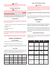
Main line gas pressure to the water heater for natural gas should be between
a maximum of 10.5" (2.59Kpa for natural gas) W.C. (14.0"/3.45Kpa for
propane) and a minimum as shown in Table 4: that is, for Natural Gas 4"
(.98Kpa) W.C. and 9.0" (1.97Kpa) for Propane Gas. The inlet gas pressure
must not exceed the maximum value. A service regulator must be installed
within 10' (305 cm) of the unit.
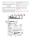
The AHCG3/HCG3100T199 and AHCG3/HCG3100T250 models incorporate
a new gas control, which operates at 0"W.C. (0kPa) for both natural and
propane gas. These models are congured prior to being shipped from the
factory and no adjustments are necessary prior to startup. The controller
monitors the air-ow and makes adjustments to the fan speed which in
effect controls the amount of gas ow. Therefore, the unit will self-adjust
to acquire the correct amount of input.
Once the unit is installed and lled with water and the inlet pressures
conrmed, simply turn the switch "on" and observe operation. Cycle the unit
"off" and "on" several times to ensure proper operation.
OPERATING INSTRUCTIONS
IMPORTANT
IT IS RECOMMENDED THAT A QUALIFIED SERVICE TECHNICIAN
PERFORM THE INITIAL FIRING OF THE HEATER. AT THIS TIME THE
USER SHOULD ASK THE TECHNICIAN ANY QUESTIONS IN REGARD
TO THE OPERATION AND MAINTENANCE OF THE UNIT.
CAUTION
BEFORE PROCEEDING WITH THE OPERATION OF THE UNIT, MAKE
SURE HEATER AND SYSTEM ARE FILLED WITH WATER AND ALL AIR
IS EXPELLED FROM HEATER AND PIPING.
NEVER OPERATE THE HEATER WITHOUT FIRST BEING CERTAIN IT IS
FILLED WITH WATER AND A TEMPERATURE AND A PRESSURE RELIEF
VALVE IS INSTALLED IN THE RELIEF VALVE OPENING OF THE HEATER.
DO NOT ATTEMPT TO OPERATE HEATER WITH COLD WATER INLET
VALVE CLOSED.
FILLING:
1. Close the heater drain valve.
2. Open a nearby hot water faucet to permit the air in the system to escape.
3. Fully open the cold water inlet pipe valve allowing the heater and piping
to be lled.
4. Close the hot water faucet as water starts to ow.
5. The heater is ready to be operated.
THE MAIN MANUAL GAS SHUTOFF VALVE MUST HAVE BEEN CLOSED
FOR AT LEAST FIVE (5) MINUTES. THIS WAITING PERIOD IS AN
IMPORTANT SAFETY STEP. ITS PURPOSE IS TO PERMIT GAS THAT
MIGHT HAVE ACCUMULATED IN THE COMBUSTION CHAMBER TO
CLEAR. IF YOU DETECT GAS AT THE END OF THIS PERIOD, DO NOT
PROCEED WITH LIGHTING. RECOGNIZE THAT GAS ODOR, EVEN IF
IT SEEMS WEAK, MAY INDICATE THE PRESENCE OF ACCUMULATED
GAS SOMEPLACE IN THE AREA WITH A RISK OF FIRE OR EXPLOSION.
SEE THE FRONT PAGE FOR STEPS TO BE TAKEN.
DO NOT USE THIS HEATER IF ANY PART HAS BEEN UNDER WATER.
IMMEDIATELY CALL A QUALIFIED SERVICE TECHNICIAN TO INSPECT
THE HEATER AND TO REPLACE ANY PART OF THE CONTROL SYSTEM
AND ANY GAS CONTROL WHICH HAS BEEN UNDER WATER.
LIGHT THE UNIT IN ACCORDANCE WITH THE OPERATING
INSTRUCTIONS LABEL ATTACHED TO THE HEATER.
THESE INSTRUCTIONS ARE REPEATED IN THE LIGHTING AND
OPERATING LABEL ILLUSTRATION ON PAGE 20 IN THIS MANUAL.
ADJUSTMENT PROCEDURE
INITIAL START-UP - AHCG3/HCG360T120 thru AHCG3/HCG3100T150
Main line gas pressure to the water heater for natural gas should be between
a maximum of 10.5" (2.59Kpa for natural gas) W.C. (14.0"/3.45Kpa for
propane) and a minimum as shown in Table 4: that is, for Natural Gas, 4.8
(1.18Kpa) W.C. and 8.5" (2.08Kpa) for Propane Gas. The inlet gas pressure
must not exceed the maximum value. A service regulator must be installed
within 10' (305 cm) of the unit.
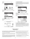
1. Check gas line pressure with a manometer.
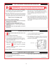
2. Check manifold pressure (see Table 4, page 20) using a pressure
gauge (manometer) connected to the manifold pressure tap on the
gas control valve, (Figure 15).
If full rate adjustment is required, remove cover screw from top of the
gas control valve, (Figure 15).
Using a small screwdriver, turn adjusting screw clockwise
to increase
or counterclockwise
to decrease gas pressure to obtain 4.0" (1 kPa)
for natural gas and 10.0" W.C. (2.5 Kpa) for L.P. Gas.
3. Cycle the burner on and off several times to check its operation.
4. Check the operation of the limit and operating controls.
3600
X 1050 = 150,000 Btuh (44 Kw)
25.25