


37
1
Integrated control module will automatically attempt to reset from lockout after one hour.
2
LED Flash code will cease if power to the control module is interrupted through the disconnect or door switch.
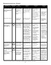
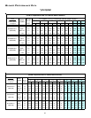
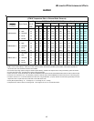
TROUBLESHOOTING CHART
• Furnace lockout due
to an excessive
number of ignition
attempts. (3 total)
1
• Auxiliary Limit Open
• Locate and correct
gas interruption.
• Replace or realign
igniter.
• Check flame sense
signal. Sand sensor
if coated and/or
oxidized.
• Check flue piping for
blockage, proper
length, elbows, and
termination.
•Verify proper
induced draft blower
performance.
• Check circulator
blower speed and
performance.
Correct speed or
replace blower if
necessary.
• Turn power OFF
prior to repair.
• Igniter is fragile,
handle with care.
• Clean flame sensor
with steel wool.
• See “Combustion
and Ventilation Air
Requirements” and
“Category I Venting
(Vertical Venting)”
section for details.
• See Product Data
Bulletin for
allowable rise
range and proper
circulator speed.
• Furnace fails to operate.
• Integrated control module
diagnostic LED is
flashing ONE (1) flash.
1
1 FLASH
• Failure to establish flame.
Cause may be no gas to
burners, bad igniter or
igniter alignment, improper
orifices, or coated/
oxidized or improperly
connected flame sensor.
• Loss of flame after
establishment. Cause may
be interrupted gas supply,
lazy burner flames
(improper gas pressure or
restriction in flue or
improper induced draft
blower performance.
• Insufficient conditioned air
over the heat exchanger.
Blocked filters, restrictive
ductwork, improper
circulator blower speed,
or failed circulator blower.
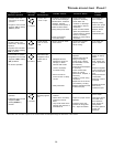
•Pressure switch
circuit is closed.
• Induced draft blower
is not operating.
• Replace induced
draft blower
pressure switch.
• Repair short.
• Turn power OFF
prior to repair.
• Replace pressure
switch with proper
replacement part.
• Furnace fails to operate.
• Integrated control module
diagnostic LED is
flashing TWO (2)
flashes.
2
2 FLASHES
•Induced draft blower
pressure switch contacts
sticking.
•Shorts in pressure switch
circuit.
•Inspect pressure switch
hose. Repair, if neces-
sary,
• Inspect flue for blockage,
proper length, elbows,
and termination.
•Correct pressure switch
setpoint or contact
motion.
• Tighten or correct wiring
connection.
• Inspect masonry
chimney and flue; remove
blockage.
•Pressure switch hose
blocked, pinched or
connected improperly.
•Blocked flue or weak
induced draft blower.
•Incorrect pressure switch
setpoint or malfunctioning
switch contacts.
•Loose or improperly
connected wiring.
•Blockage in flue or
chimney.
•Pressure switch
circuit not closed.
• Induced draft blower
is operating.
• If installed, manual
reset limit switch is
open on Masonry
Vent Kit (MVK).
• Induced draft blower
runs continuously with
no further furnace
operation.
• Integrated control module
diagnostic LED is
flashing THREE (3)
flashes.
3
3 FLASHES
• Turn power OFF
prior to repair.
• See “Combustion
and Ventilation Air
Requirements” and
“Category I Venting
(Vertical Venting)”
section for details.
• Replace pressure
switch with proper
replacement part.
• Replace masonry
vent kit limit switch
with correct
replacement part.
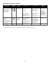
• Integrated control
module has an
internal fault.
• Integrated control module
has an internal fault.
• Replace bad integrated
control module.
• Turn power OFF
prior to repair.
• Read precautions
in “Electrostatic
Discharge” section
of manual.
• Furnace fails to operate.
• No 115 volt power to
furnace, or no 24
volt power to
integrated control
module.
• Blown fuse or circuit
breaker.
•Manual disconnect switch
OFF, door switch open, or
24 volt wires improperly
connected or loose.
•Blown fuse or circuit
breaker.
• Assure 115 and 24 volt
power to furnace
integrated control
module.
• Check integrated control
module fuse (3A).
Replace if necessary.
• Check for possible
shorts in 115 and 24 volt
circuits. Repair as
necessary.
• Turn power OFF
prior to repair.
• Replace integrated
control module
fuse with 3A
automotive fuse.
• Furnace fails to operate.
• Integrated control module
diagnostic LED provides
no signal.
NONE
Cautions
& Notes
Corrective
Action
Possible
Causes
Fault
Description(s)
Symptoms of
Abnormal Operation
Associated
LED Code
2