


23
S
TART
-
UP
P
ROCEDURE
AND
A
DJUSTMENT
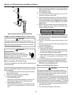
nace and the cooling coil. This reading is usually taken by
removing the “A” shaped block off plate from the end on the
coil; drilling a test hole in it and reinstalling the block off plate.
Take a duct static reading at the test hole. Tape up the test
hole after your test is complete. The negative pressure must be
read between the filter and the furnace blower.
Too much external static pressure will result in insufficient air
that can cause excessive temperature rise. This can cause
limit switch tripping and heat exchanger failure.
To determine total external duct static pressure, proceed as
follows;
1. With clean filters in the furnace, use a draft gauge
(inclined manometer) to measure the static pressure of
the return duct at the inlet of the furnace. (Negative
Pressure)
2. Measure the static pressure of the supply duct. (Positive
Pressure)
3. The difference between the two numbers is .4” w.c.
Example:
static reading from return duct = -.1" w.c.
static reading from supply duct = .3" w.c.
total external static pressure on this system = .4" w.c.
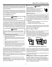
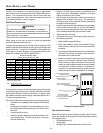
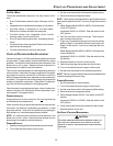
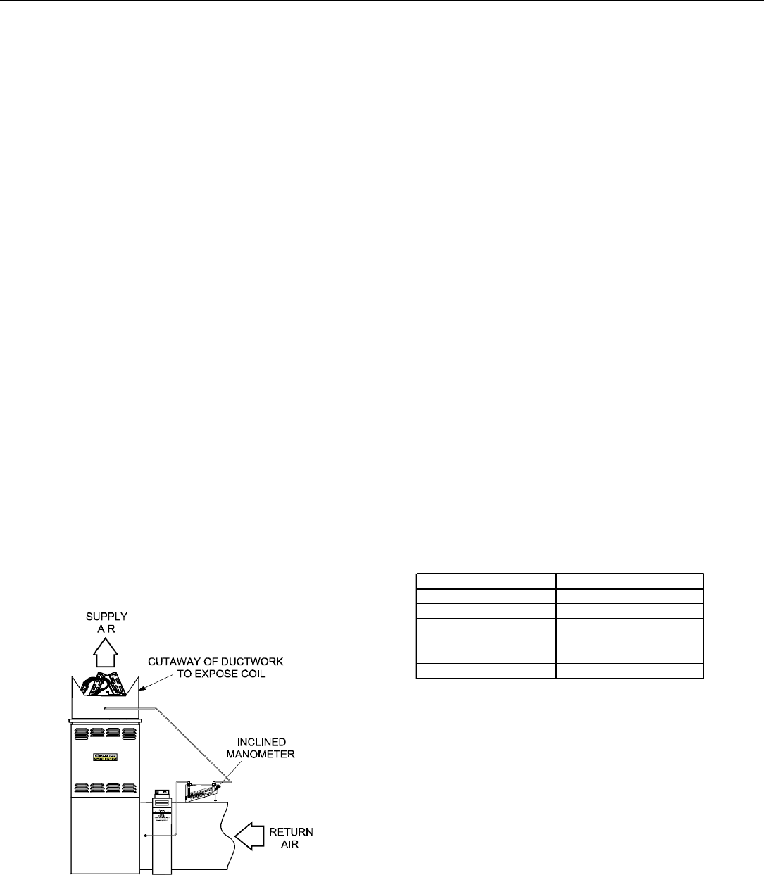
NOTE: Both readings may be taken simultaneously and read
directly on the manometer if so desired. If an air conditioner
coil or Electronic Air Cleaner is used in conjunction with the
furnace, the readings must also include theses components,
as shown in the following drawing.
4. Consult proper tables for the quantity of air.
If the total external static pressure exceeds the maximum listed
on the furnace rating plate, check for closed dampers, regis-
ters, undersized and/or oversized poorly laid out duct work.
Checking Static Pressure
(80% Furnace Shown, 90% Similar)
FILTERS - READ T HIS S ECTION B EFORE I NSTALLING T HE
RETURN A IR DUCTWORK
Filters must be used with this furnace. Discuss filter mainte-
nance with the building owner. Filters do not ship with this
furnace, but must be provided by the installer. Filters must com-
ply with UL900 or CAN/ULCS111 standards. If the furnace is
installed without filters, the warranty will be voided.
NOTE: An undersized opening will cause reduced airflow. The
bottom return is set up as a knock out.
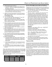
UPRIGHT I NSTALLATIONS
Depending on the installation and/or customer preference, dif-
fering filter arrangements can be applied. Filters can be in-
stalled in the central return register or a side panel external
filter rack kit (upflows), or the ductwork above a downflow fur-
nace. As an alternative, a media air filter or electronic air cleaner
can be used as the primary filter.
CIRCULATION A IR F ILTERS
One of the most common causes of a problem in a forced air
heating system is a blocked or dirty filter. Circulating air filters
must be inspected monthly for dirt accumulation and replaced
if necessary. Failure to maintain clean filters can cause prema-
ture heat exchanger failure.
A new home may require more frequent replacement until all
construction dust and dirt is removed. Circulating air filters are
to be installed in the return air duct external to the furnace
cabinet.
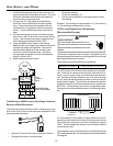
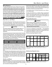
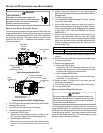
FURNACE INPUT FILTER SIZE
40M
320 in
2
60M
483 in
2
80M
640 in
2
100M
800 in
2
120M
738 in
2
140M
738 in
2
DISPOSABLE NOMINAL 300 F.M. FACE VELOCITY
MINIMUM FILTER SIZES for DISPOSABLE FILTERS
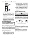
HORIZONTAL I NSTALLATIONS
Filters must be installed in either the central return register or
in the return air duct work.
S
EQUENCE
OF
O
PERATION
(I
NTEGRATED
I
GNITION
C
ONTROL
)
Refer to Timing Charts for sequencing.
NOTE: Dip switch positions referenced in this section applies
to *(M,D)H8 models only.
POWER U P
• 115 VAC power applied to furnace.
• Integrated ignition control performs internal checks.
• Integrated ignition LED will light.