


11
E
XTERIOR
MASONRY
C
HIMNEYS
- C
ATEGORY
I F
URNACES
O
NLY
Code NFPA 54/ANSI Z223.1 or CAN/CSA B149 Installation
Codes or applicable provisions of the local building codes for
determining the combustion air requirements for the appliances.
This furnace must use indoor air for combustion. It cannot be
installed as a direct vent (i.e., sealed combustion) furnace.
Most homes will require outside air be supplied to the furnace
area by means of ventilation grilles or ducts connecting directly
to the outdoors or spaces open to the outdoors such as attics
or crawl spaces.
C
ATEGORY
I V
ENTING
(V
ERTICAL
V
ENTING
)
T
O
PREVENT
POSSIBLE
PERSONAL
INJURY
OR
DEATH
DUE
TO
ASPHYXIATION
,
THIS
FURNACE
MUST
BE
C
ATEGORY
I
VENTED
.D
O
NOT
VENT
USING
C
ATEGORY
III
VENTING
.
WARNING
Category I Venting is venting at a non-positive pressure. A
furnace vented as Category I is considered a fan-assisted ap-
pliance and the vent system does not have to be “gas tight.”
NOTE: Single stage gas furnaces with induced draft blowers
draw products of combustion through a heat exchanger allow-
ing, in some instances, common venting with natural draft ap-
pliances (i.e. water heaters). All installations must be vented in
accordance with National Fuel Gas Code NFPA 54/ANSI Z223.1
- latest edition. In Canada, the furnaces must be vented in ac-
cordance with the National Standard of Canada, CAN/CSA
B149.1 and CAN/CSA B149.2 - latest editions and amendments.
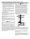
NOTE: Masonry vent kit (MVK-01 and MVK-02) is to only be
used on interior masonry chimneys or qualifying exterior
masonry chimney applications identified in the MVK kit
installation instructions. To ensure safe and reliable operation,
use only the kit listed for your model.
NOTE: The vertical height of the Category I venting system
must be at least as great as the horizontal length of the venting
system.
T
O
PREVENT
POSSIBLE
PERSONAL
INJURY
OR
DEATH
DUE
TO
ASPHYXIATION
,
COMMON
VENTING
WITH
OTHER
MANUFACTURER
’
S
INDUCED
DRAFT
APPLIANCES
IS
NOT
ALLOWED
.
WARNING
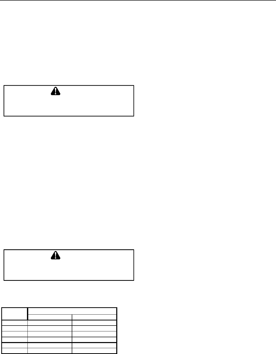
The minimum vent diameter for the Category I venting system
is as shown:
UPFLOW COUNTERFLOW
40 4 Inch 4 Inch
60 4 Inch 4 Inch
80 4 Inch 4 Inch
100 5 Inch 5 Inch
120 5 Inch N/A
140 5 Inch N/A
MODEL
MINIMUM VENT
Under some conditions, larger vents than those shown above
may be required or allowed. When an existing furnace is re-
moved from a venting system serving other appliances, the
venting system may be too large to properly vent the remaining
attached appliances.
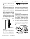
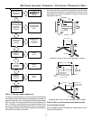
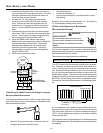
Upflow or Horizontal units are shipped with the induced draft
blower discharging from the top of the furnace. (“Top” is as
viewed for an upflow installation.) The induced draft blower can
be rotated 90 degrees with the (0270F01119) chimney transi-
tion bottom kit for Category I venting. For horizontal installa-
tions, a four inch single wall pipe can be used to extend the
induced draft blower outlet 1/2” beyond the furnace cabinet.
THIS PRODUCT IS NOT DESIGNED FOR COUNTERCLOCK-
WISE INDUCED DRAFT BLOWER ROTATION.
Vent the furnace in accordance with the National Fuel Gas
Code NFPA 54/ANSI Z223.1 - latest edition. In Canada, vent
the furnace in accordance with the National Standard of Canada,
CAN/CSA B149.1 and CAN/CSA B149.2 - latest editions and
amendments.
Venting - Furnace Installed in Horizontal Position
THIS FURNACE IS NOT DESIGN CERTIFIED TO BE HORI-
ZONTALLY VENTED THROUGH AN EXTERIOR SIDE WALL.
The following describes an optional venting procedure when the
furnace is installed in the horizontal left discharge position.
To rotate the induced draft blower clockwise, you will need to
purchase one (0270F01119) chimney transition bottom kit.
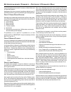
1. Disconnect electrical power from the furnace.
2. Disconnect the induced draft blower power leads, flue
pipe, and pressure switch tubing.
3. Remove the round cutout from the right side of the wrapper.
4. Remove and save the four screws that fasten the induced
draft blower to the flue collector box.
5. Remove and save the three screws that hold the chimney
assembly to the induced draft blower.
6. Remove and save the four screws that fasten the chimney
top to the chimney bottom.
7. Remove the chimney transition bottom from the transition
bottom kit.
8. Install the chimney top with the four screws retained
from step 6 onto the new chimney transition bottom from
the transition bottom kit.
9. Remove the induced draft blower and install the new
chimney assembly to it using the three screws retained
from step 5.
10. Rotate the induced draft blower 90 degrees to the right,
feed the flue pipe through the round cutout from the outside
of the wrapper, and fit onto the chimney top assembly.
Secure the pipe to the chimney top from the front, top,
and bottom using (3) screws and rotating the induced