


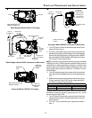
31
S
TART
-
UP
P
ROCEDURE
AND
A
DJUSTMENT
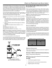
Setting the Mode switch to “2 STG” allows the furnace to
operate at the furnace’s highest input AND at an input rate
that is 75% of the highest input rate. For this mode of
operation, the furnace operates at the low input rate for a
pre-determined time period then steps to the high input rate.
Operation is as described under Sequence of Operation
(Integrated Ignition Control) – Mode DIP Switch is set to “2
STG” position.
The time period is determined by the 2
nd
Stg Dly DIP switch.
Setting the 2
nd
Stg Dly DIP switch to 5 minutes fixes the
delay period at 5 minutes. Setting the 2
nd
Stg Dly DIP
switch to Auto enables an algorithm that calculates a delay
period based on the heating cycle time and the total cycle
time. The delay period can range from 1 minute to 12
minutes.
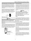
5 MIN
OFF
ON
1 STG
AUTO
2 STG
M
2
ND
STG DLY
O
PERATIONAL
C
HECKS
WARNING
T
O AVOID PERSONAL INJURY OR DEATH, DO NOT REMOVE ANY INTERNAL
COMPARTMENT COVERS OR ATTEMPT ANY ADJUSTMENT.
E
LECTRICAL
COMPONENTS ARE CONTAINED IN BOTH COMPARTMENTS.
C
ONTACT A
QUALIFIED SERVICE AGENT AT ONCE IF AN ABNORMAL FLAME APPEARANCE
SHOULD DEVELOP.
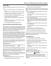
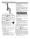
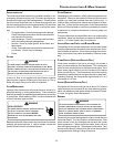
BURNER F LAME
The burner flames should be inspected with the burner com-
partment door installed. Flames should be stable, quiet, soft,
and blue (dust may cause orange tips but they must not be
yellow). Flames should extend directly outward from the burn-
ers without curling, floating, or lifting off. Flames must not
impinge on the sides of the heat exchanger firing tubes.
Check the burner flames for:
1. Good adjustment
2. Stable, soft and blue
3. Not curling, floating, or lifting off.
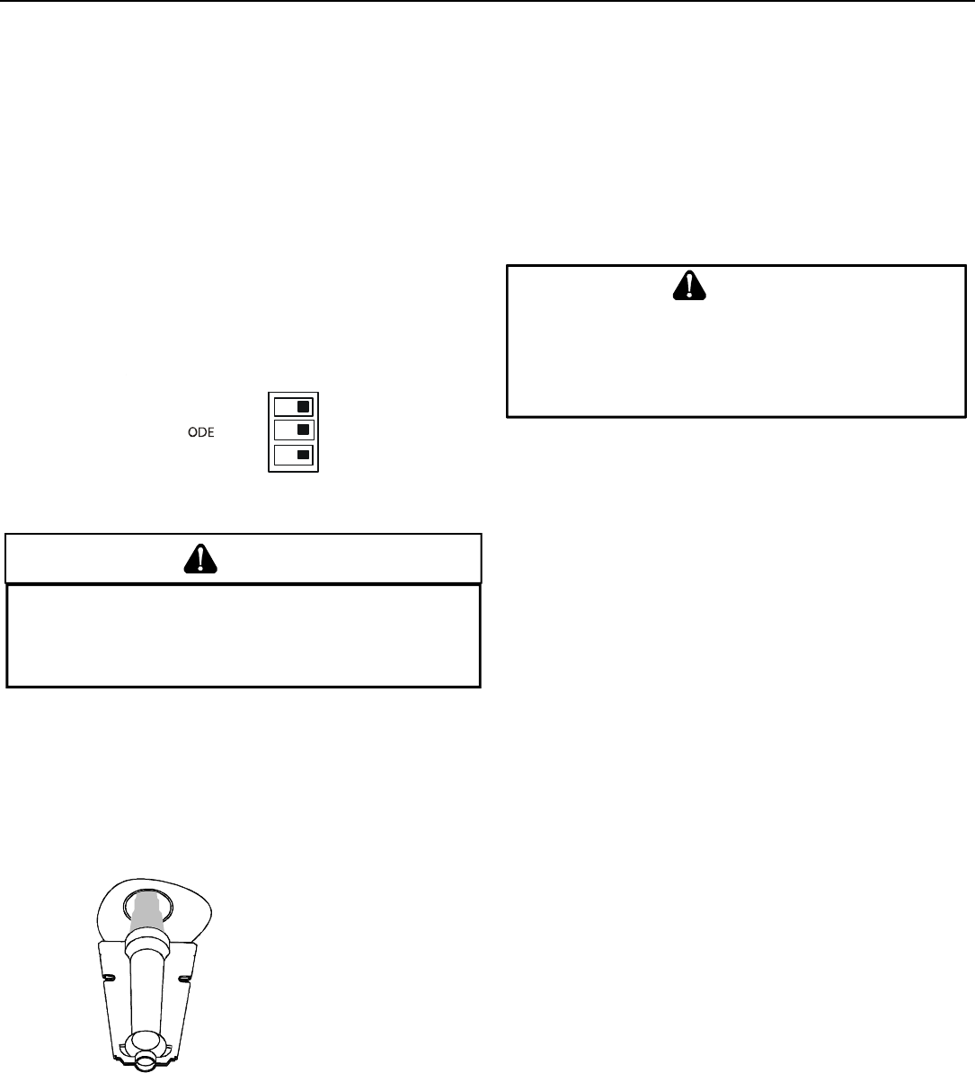
Burner Flame
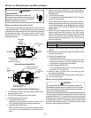
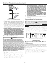
AUXILIARY L IMIT CONTROL
Auto reset limits are located on or near the blower. To access
this auxiliary limit, disconnect the electrical power and remove
the blower door. The auxiliary limit control is designed to pre-
vent furnace operation in case of main blower failure on hori-
zontal installations. It may also open if the power supply is
interrupted while the furnace is firing. The auxiliary limit control
is suitable for both horizontal right and horizontal left installa-
tions. Regardless of airflow direction, it does not need to be
relocated.
T
O
AVOID
PERSONAL
INJURY
OR
DEATH
,
DO
NOT
REMOVE
ANY
INTERNAL
COMPARTMENT
COVERS
OR
ATTEMPT
ANY
ADJUSTMENT
.
E
LECTRICAL
COMPONENTS
ARE
CONTAINED
IN
BOTH
COMPARTMENTS
.
C
ONTACT
A
QUALIFIED
SERVICE
AGENT
AT
ONCE
IF
AN
ABNORMAL
FLAME
APPEARANCE
SHOULD
DEVELOP
.
WARNING
S
AFETY
C
IRCUIT
D
ESCRIPTION
GENERAL
A number of safety circuits are employed to ensure safe and
proper furnace operation. These circuits serve to control any
potential safety hazards and serve as inputs in the monitoring
and diagnosis of abnormal function. These circuits are con-
tinuously monitored during furnace operation by the integrated
control module.
INTEGRATED C ONTROL M ODULE
The integrated control module is an electronic device which
controls all furnace operations. Responding to the thermostat,
the module initiates and controls normal furnace operation, and
monitors and addresses all safety circuits. If a potential safety
concern is detected, the module will take the necessary pre-
cautions and provide diagnostic information through an LED.
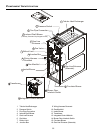
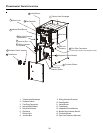
PRIMARY LIMIT
The primary limit control is located on the partition panel and
monitors heat exchanger compartment temperatures. It is an
automatic reset, temperature sensor. The limit guards against
the overheating resulting from insufficient air passing over the
heat exchanger.
AUXILIARY L IMIT
The auxiliary limit control is located either on or near the circu-
lator blower and monitors heat exchanger compartment tem-
peratures. The control is an automatic reset, temperature
sensor. It guards against overheating resulting from insufficient
air passing over the heat exchanger.