


18
G
AS
S
UPPLY
AND
P
IPING
1. Install the field supplied relay on the control mount-
ing panel near the furnace ignition control. The relay
should be installed such that the motor leads will
reach the relay contact terminals.
2. Connect the “Y2” (high stage cool) thermostat
terminal to one coil terminal of the field supplied
relay. Connect the other field supplied relay coil
terminal to the “C” terminal on the furnace ignition
control. Typical 18AWG thermostat wire may be
used.
3. Connect the common terminal of the field supplied
relay to the “LINE-H” terminal on the furnace ignition
control. Use wiring having copper conductors only
and a temperature rating of at least 105°C.
4. Using the GME8 airflow tables in this manual,
determine the motor speed tap needed to deliver the
required high stage cooling airflow. Connect the
selected motor speed tap to the normally open
terminal on the field supplied relay. Use wiring
having copper conductors only and a temperature
rating of at least 105°C.
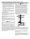
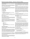
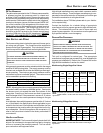
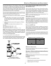
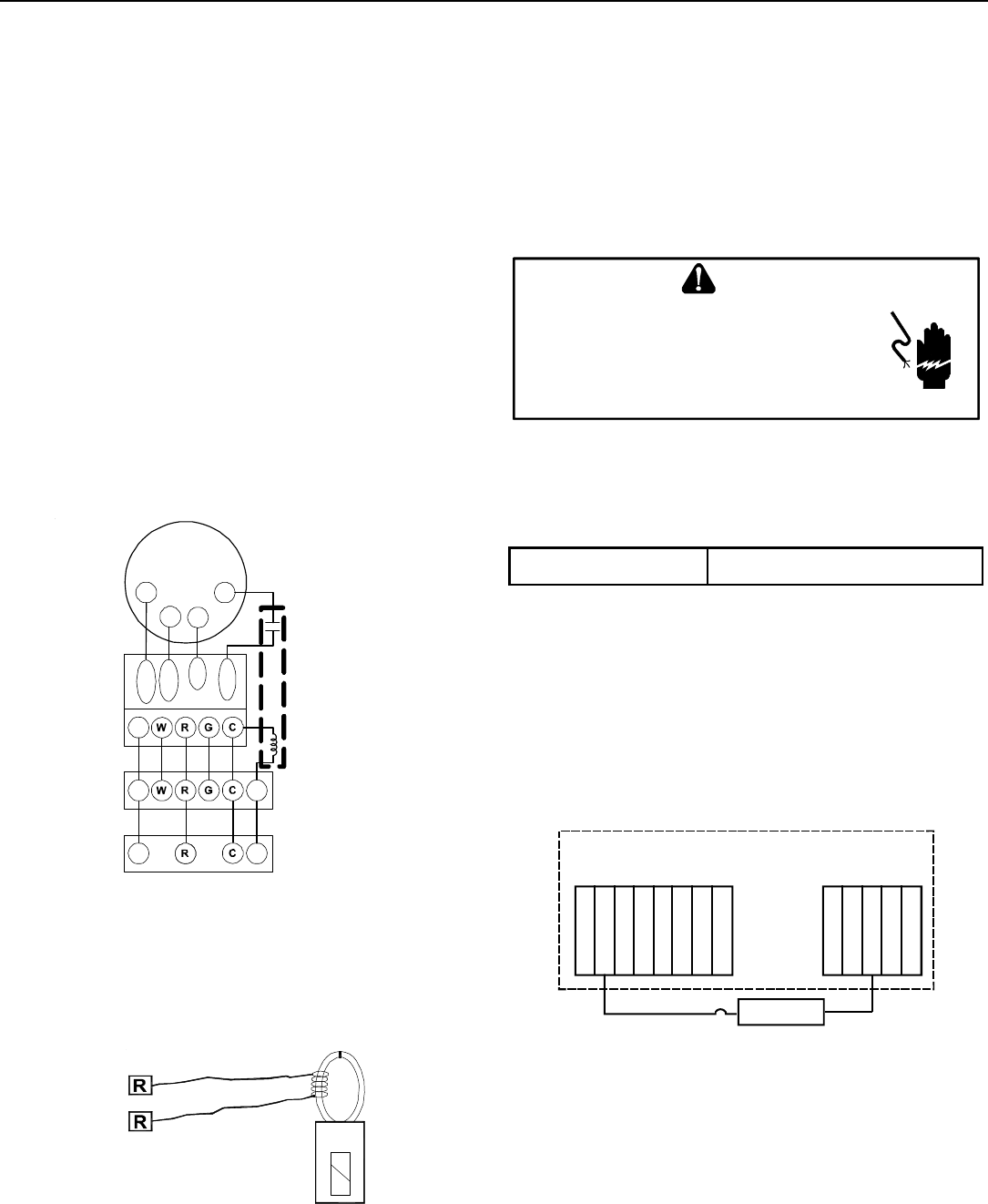
5. See the wiring schematic below.
Furnace
Control
Remote Condensing Unit
Heating/Cooling
Room Thermostat
Y
Y1
Y1 Y2
Lo-Heat
Hi-Heat
Cool
Line-H
T4
T2
T3
T5
ECO-TECH
MOTOR
Field
Supplied
Relay
Y2
Field Wiring for GME8 Furnace with 2-Stage Condenser
SETTING THE H EAT A NTICIPATOR
The following method should be used in measuring the amp
draw of the control circuit to assure proper adjustment of the
thermostat heat anticipator
• Wrap the “R” leg around a clip-on ammeter 10 times.
• Energize the furnace in the heat mode.
• Record the reading.
• Divide this reading by 10.
• Set the heat anticipator on the thermostat to match
this reading.
Example: If the reading on the ammeter is “4”, divide this by
10. The anticipator setting will be .4 amps.
115 VOLT L INE C ONNECTION OF A CCESSORIES
(ELECTRONIC A IR C LEANER)
HIGHVOL TAGE!
T
O
AVOID
PERSONAL
INJURY
OR
DEATH
DUE
TO
ELECT RICAL
SHOCK
,
DISCONNECT
ELECT RICAL
POWER
BEFORE
SERVICING
OR
CHANGING
ANY
ELECT RICAL
WIRING
.
WARNING
The furnace integrated control module is equipped with line
voltage accessory terminals for controlling power to an optional
field-supplied electronic air cleaner.
The accessory load specifications are as follows:
Electronic Air Cleaner 1.0 Amp maximum at 120 VAC
Turn OFF power to the furnace before installing any accesso-
ries. Follow the air cleaner manufacturers’ instructions for lo-
cating, mounting, grounding, and controlling these accesso-
ries. Accessory wiring connections are to be made through
the 1/4" quick connect terminals provided on the furnace inte-
grated control module. The electronic air cleaner hot terminal
is identified as EAC-H and the neutral terminal is identified as
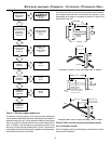
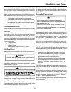
NEUTRAL. All field wiring must conform to applicable codes.
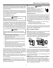
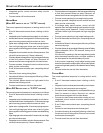
Connections should be made as shown in the following illustra-
tion.
EAC-H
Line
Transformer
Line
Transformer
EAC
Air Cleaner
Control Module
Hot 120 VAC
Neutral 120 VAC
Optional
Accessories
If it is necessary for the installer to supply additional line volt-
age wiring to the inside of the furnace, the wiring must conform
to all local codes, and have a minimum temperature rating of
105°C. All line voltage wire splices must be made inside the
furnace junction box.
The integrated control module electronic air cleaner terminals
(EAC) are energized with 115 volts whenever the circulator blower
is energized.