


5
NOTE: The Rail/Chain Assembly is
packaged separately from the Power
Head Unit. The trolley, front idler/
tension adjustment assembly, chain,
drive gear and limit cams are assembled
to the Rail/Chain Assembly at the
factory. Follow the steps outlined
below to complete assembly prior to
installation. Refer to the component
identification illustrations on the
previous page.
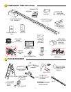
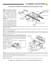
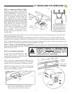
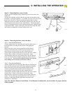
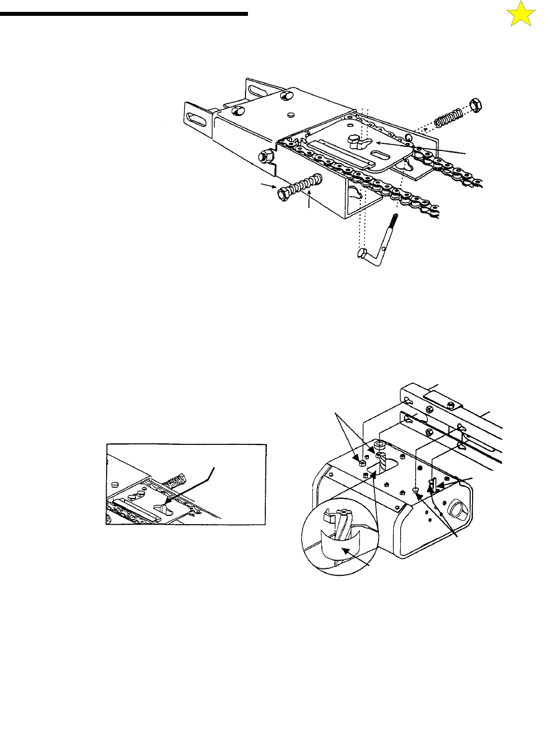
STEP 1: Prior to attaching the motor
drive unit to the rail assembly, the Open
and Close adjustment bolts must be
installed. Place the threaded end of the
adjustment bolt through the hole in the
rail and then slip the head of the bolt
through the center of the double key
hole. Slide the spring over the bolt and attach load adjusting nut. Tighten until the tip of the bolt extends 3/16” outside the nut. Repeat
above for the other side.
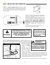
STEP 2: Protect the Power Unit cover from scratching during assembly by placing it on cardboard. Loosen the two 5/16" lock washer
nuts on top of the power head drive unit.
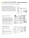
STEP 3: VERY IMPORTANT ! Position a paper shim around the power head unit drive gear (standard weight paper, see
illustration). Shim must remain in place while assembling the power head unit to the Rail/Chain assembly to ensure a proper gear mesh
and avoid excessive long term wear.
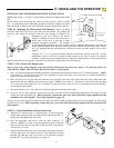
STEP 4: Align the four key holes in the Rail/Chain assembly with
the two front guide tabs and the two rear bolt studs on the power head
unit and place the rail/chain assembly in place over the power head
unit. The power head drive unit limit lever protrudes up through the
rail/chain assembly sensing plate. Take care not to bend the lever
when assembling. Slide
the power head drive
unit forward until the
gear meshes with the
rail/chain assembly
drive gear. Check to
make sure the front
guide tabs on the power
head unit are securely
locked on the rail/chain
assembly.
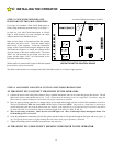
STEP 5: The power head drive unit should be move forward until all play between the gears has been eliminated, but no additional
force should be used that could cause pressure on the motor (power head unit) drive gear. Tighten the two 5/16" lock washer nuts on
top of the power head drive unit that were loosened in Step 2 above.
When the opener is first activated the paper shim will be ejected. The paper shim should have the profile of the gears to indicate the
proper mesh between them.
STEP 6: Recheck the nuts used to secure the Rail/Chain assembly to the Power Head Unit, making sure they are tight.
Assembly is now complete and you are ready to begin installation of the opener.
If Your Opener Is Supplied Fully Assembled, Please Disregard This Page.
A: ASSEMBLY INSTRUCTIONS
Assembled and
In Position
Spring
Spring
Force Adjusting
Plastic-Insert
Locking Nut
L-Shaped Adjustment Bolt
Double Key Hole
Limit Lever
Take care not to
bend limit lever
5/16” Lock
Washer Nuts
110047-1
110047-3
110047-2
Limit
Lever
Front Guide
Tabs (2)
Paper Shim