


10
C: INSTALLING THE OPERATOR
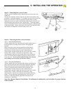
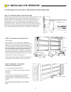
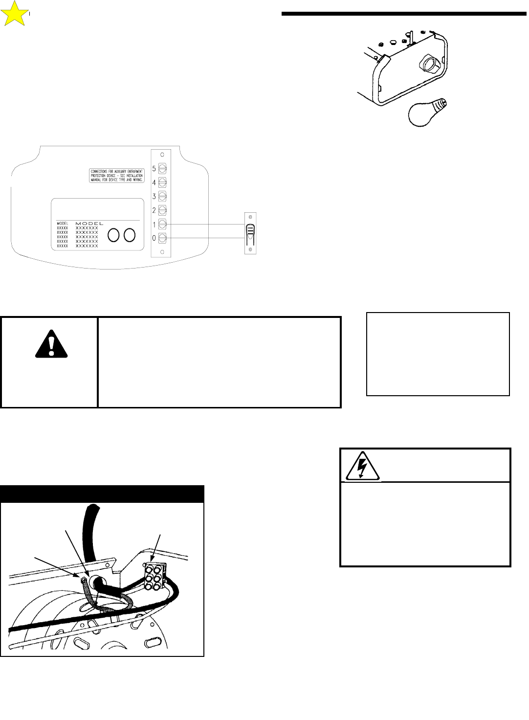
STEP 7: Install a Rough Service lamp bulb (75 Watt
maximum) firmly in the light socket. Light bulbs in Door Openers are
subject to vibration during normal operation which may shorten their
life spans. Rough Service bulbs, available at most hardware stores,
are recommended.
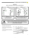
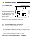
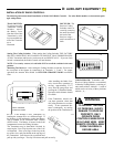
STEP 8: Connect the standard wall Push Button
provided to Terminals 1 & 0
on the Opener's rear
panel using a length of 2-conductor, minimum 22 gauge
wire. For mounting the standard Push Button, select a
convenient location near an access door. MOUNT AT
LEAST 5 FT FROM THE FLOOR TO
DISCOURAGE UNAUTHORIZED OPERATION OF
THE DOOR. Install the push button warning label (as
shown below) supplied with the Opener near this
installation.
If you are installing a Deluxe Wall Push Button), See
Page 19 for the proper wiring procedure.
WARNING
UNAUTHORIZED OPERATION OF THE DOOR
CONTROLS RISKS INJURY OR DEATH . DO NOT
ALLOW ANYONE UNFAMILIAR WITH THE DOOR
OPERATION TO OPERATE ANY DOOR
CONTROLS. MOUNT THE PUSHBUTTON AT
LEAST 5 FT FROM THE FLOOR.
104350
110051-3
108385
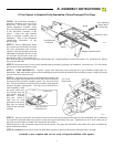
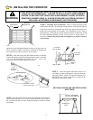
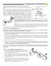
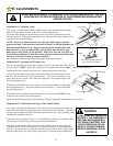
STEP 9: Connecting The Electrical Power Consult the label on the rear
panel of the Opener to determine its proper working voltage. Normally it will be
marked for 115V, 60 cycle operation. (If it is a 230V model the label will clearly
indicate this.) The Opener
must be permanently
wired with a proper
ground connection
according to all
applicable local, state,
and federal building and
electrical codes. Run a
three (3) conductor
(minimum #14, copper
conductors only) wire from a 15 AMP circuit breaker to the operator in a
suitable conduit. Use an appropriate connector to secure the conduit to the
operator chassis as shown. Connect the incoming line and neutral power
wires (L1 and L2) at the terminal block according to the diagram. Secure the
incoming earth ground to the chassis ground screw as shown .
NOTE: GFI protection is recommended especially on steel door applications.
IMPROPER WIRING COULD
CAUSE ELECTROCUTION
OR DAMAGE TO CIRCUITRY.
FOLLOW LOCAL BUILDING
AND ELECTRICAL CODES.
WARNING
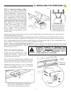
Use an appropriate
conduit connector
L1 & L2
Connections
Ground Wire &
Chassis Connection
110442
Permanent Wiring Connection
This door is operated by
a limited duty operator.
To prevent the motor
protector from tripping -
Do not exceed 6 door
cycles per hour.