


15
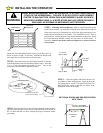
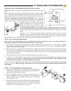
WARNING
TO PREVENT THE RISK
OF PERSONAL INJURY,
DAMAGE TO DOOR OR
PROPERTY, ONLY
OPERATE DOOR
CONTROLS WHEN DOOR
IS IN CLEAR VIEW. KEEP
REMOTE CONTROL AWAY
FROM CHILDREN IN
SECURE AREA.
104386
D: AUXILIARY EQUIPMENT
Setting The Coding Switches: When setting the Coding Switches THE FACTORY
PRE-SET CODES MUST BE CHANGED TO PREVENT UNAUTHORIZED OPER-
ATION. Transmitter and Receiver codes must be set IDENTICALLY. If just one Code
Switch is mismatched, the Radio Controls will not function.
NOTE: For security reasons, it is advisable NOT to set all the switches in the same
position.
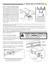
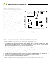
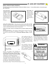
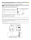
Mounting The Receiver: After setting the Coding Switches, mount the Receiver on
the rear panel of the Opener by connecting it to Terminals 1, 2 and 3. For proper
operation, the Antenna Wire should be POINTED STRAIGHT DOWN toward the
floor.
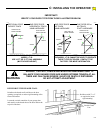
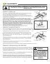
After installing the Radio Con-
trols, check their operation by
moving approximately 35 FT
away from the garage door and
pressing the Transmitter Button.
Operation at this distance should
be reliable.
If the Transmitter doesn't acti-
vate door operation, check that
all Coding Switches are set iden-
tically. If the operational dis-
tance is inadequate, try moving
the position of the Transmitter in
the car. If the distance is still inadequate, try
bending the Antenna Wire to a different angle. If
the distance is still inadequate, replace the Battery
with a standard 9-Volt “transistor radio” Battery
(NEED 1604). The Battery is located in the front
compartment next to the Coding Switches.
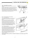
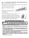
The Transmitter may be hand held if desired by
removing the Visor Clip from the rear of the Case
as illustrated. Place your finger in the loop at the
top of the visor, and your thumb on the top edge of
the Transmitter. Push down with your thumb and
pull up with your finger. The clip will release and pull out easily.
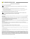
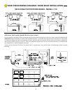
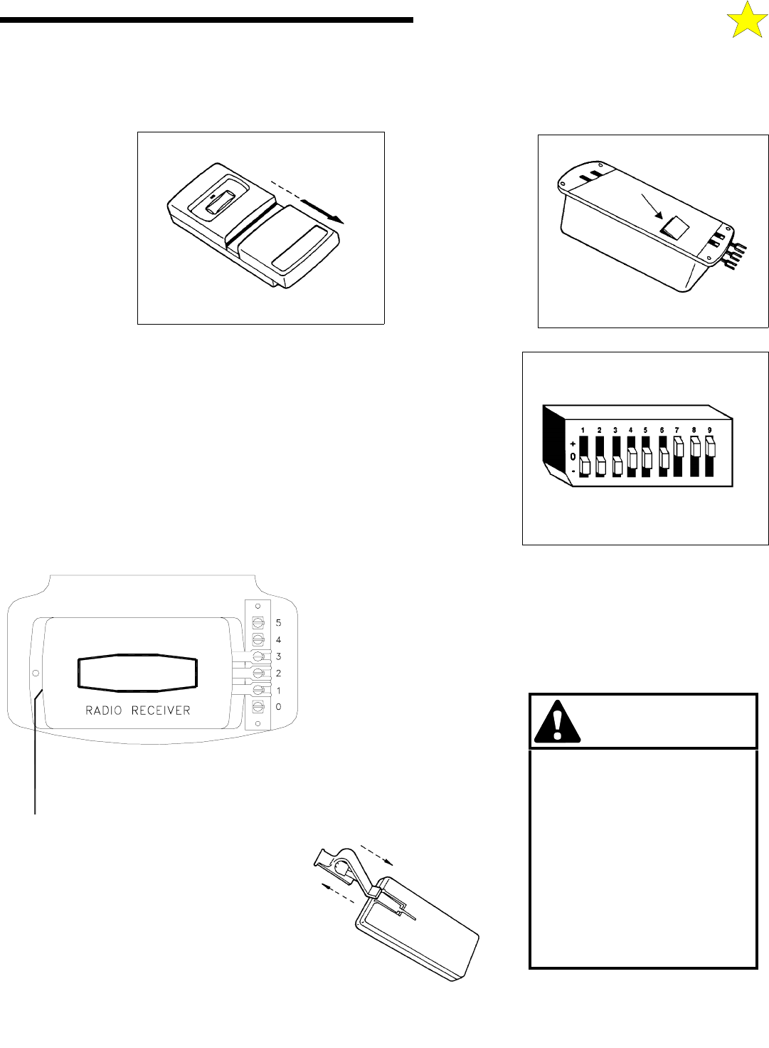
CODING BLOCK: Transmitter and
Receiver Coding Switches are contained
in identical Coding Blocks, consisting of
nine small switches, labeled 1 - 9, each of
which can be set in any of three positions,
labeled +, 0, -
POINT ANTENNA
STRAIGHT DOWN
108386
104388
INSTALLATION OF RADIO CONTROLS:
The following instructions detail installation of Model 9931 Radio Controls. For other Radio models, see instructions pack-
aged with product.
104385
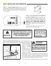
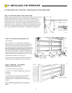
TRANSMITTER:
To gain access to the
Transmitter Coding
Switches, remove
the Battery Cover
from the front of the
Transmitter by slid-
ing it toward the bot-
tom of the Transmit-
ter as
illustrated.
104384
RECEIVER: The
Receiver Coding
Switches can be ac-
cessed by removing
the small door from
the back of the
Receiver using a
small screwdriver or
knife.