


506248-01 Page 9 of 14Issue 0902
There is no blower “on” delay after a call for heating or
cooling. Blower “off” delay is 90 seconds after the thermostat
is satisfied.
Variable Speed Motor
Units equipped with a variable speed circulation air blower
motor will deliver a constant airflow within a wide range of
external static pressures. Other features of this variable
speed motor include:
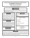
Soft Start/Stop – The variable speed motor will slowly ramp
up to normal operating speed. This minimizes noise and
increases comfort by eliminating the initial blasts of air
encountered with standard motors. At the end of a cooling
or heating cycle, the motor will slowly ramp down.
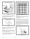
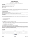
Circulation Airflow Adjustments – The controls include a
variable speed motor interface board. The ADJUST tap can
be used to raise (+) or lower (–) the airflow by 15%.
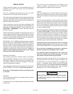
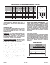
Heating and Cooling Airflows – The units are factory set
for the correct heating and cooling airflows. However, airflow
changes can be made by moving the position of the HEAT
and COOL taps (see Table 4).
Continuous Blower – The comfort level of the living space
can be enhanced when using this feature by allowing
continuous circulation of air between calls for cooling or
heating. The continuous circulation of air occurs at half the
full cooling airflow rate. To use this feature, place the
thermostat fan switch into the ON position.
Cooling Airflow Ramp Up – At the beginning of a call for
cooling, the blower will run at 80% of full airflow for 7.5
minutes. This improves the system’s moisture removal and
saves blower power during cooling start.
Reduced Airflow Operation (Dehumidification) – For
situations where humidity control is an issue, the variable
speed motor can be connected to operate at a 25% reduction
in the normal airflow rate. The variable speed motor interface
board provides for connection of a humidistat on the HUM
terminal. When a humidistat is connected, the dehumidifier
resistor on the interface must be cut. The humidistat should
be wired to open during high humidity, which will reduce
blower airflow.
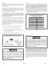
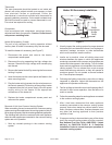
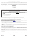
Cooling System Performance
For maximum performance of the cooling system, operating
temperatures and pressure should be checked. Subcooling
should be determined at Standard ARI test conditions of 82°F
outdoor and 80°F indoor dry bulb/67°F wet bulb. If subcooling
measured deviates from values found in Table 5, refrigerant
charge should be adjusted accordingly for maximum
performance.
ledoM
rotoM
PH
TSUJDA
gnitteS
TAEH
gnitteS
LOOC
gnitteS
MFC
A
MFC
B
MFC
C
MFC
D
lanimoN
gnilooC
UTBk
gnitaeH
eziS
Wk
4201-53/1MRONBB0001008006009
03 01-5 3/1 MRON A A 0001 008 006 009
6351-52/1MRONAA002100010080011
24 02-5 4/3 MRON C C 0081 0061 0041 0021
8402-54/3MRONBB0081006100410021
06 02-5 4/3 MRON A A 0081 0061 0041 0021
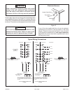
Adjusting Airflow (Variable Speed Motor Equipped Units Only)
Table 4
DEHUMIDIFY
CUT TO ENABLE
COOLHEATADJUST
NORM A
B
C
D
A
B
C
D
(+)
(–)
TEST
D1
ADJUST, HEAT, and
COOL Taps
and Dehumidify
Resistor on
Interface Board
Liquid Subcooling
Table 5
eziS
gniloocbuSdiuqiL
snoitidnoCIRA@
BWDI°76/BDDI°08-DO°28
22R A014
42°01°9
03 °8 °11
63°01°11
84,24 °5 °7
06°01°01