


Page 6 of 14 506248-01Issue 0902
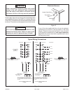
Thermostat
The room thermostat should be located on an inside wall
where it will not be subject to drafts, sun exposure, or heat
from electrical fixtures or appliances. Follow the
manufacturer’s instructions enclosed with thermostat for
general installation procedure. Color-coded insulated wires
(#18 AWG) should be used to connect thermostat to unit.
Four wires are required for cooling.
Compressor
Units are shipped with compressor mountings factory-
adjusted and ready for operation. Caution: Do not loosen
compressor mounting bolts.
Heater Kit Accessory (if used)
The unit is fully equipped for cooling operation without
auxiliary heat. A heater kit accessory may also be used.
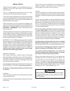
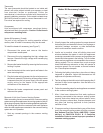
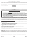
To install the heater kit accessory (see Figure 7):
1. Disconnect the power and remove the heater
compartment access panel.
2. Disconnect the plug separating the high voltage wire
harness. Remove the high voltage wire harness plug
and discard.
3. Remove the heater blockoff by removing the four screws
holding it in place.
4. Insert the heater into the control panel and fasten in the
same mounting holes.
5. Plug the heater wiring harness into the wire harness on
the control assembly. Field wiring of the auxiliary heater
is separate from the unit power supply. Wire the power
supply wiring for the heater to the appropriate
connections on the heater kit.
6. Replace the heater compartment access panel and
reconnect the power.
Removal of Unit from Common Venting System
When an existing furnace is removed from a common venting
system serving other appliances, the venting system is likely to
be too large to properly vent the remaining attached appliances.
The following test should be conducted with each appliance
while the other appliances connected to the common venting
system are not in operation.
1. Seal any unused openings in the common venting
system.
2. Visually inspect the venting system for proper size and
horizontal pitch and determine there is no blockage or
restriction, leakage, corrosion, or other deficiencies
which could cause an unsafe condition.
3. Insofar as is practical, close all building doors and
windows between the space in which the appliances
remaining connected to the common venting system are
located and other spaces in the building. Turn on clothes
dryers and any appliance not connected to the common
venting system. Turn on exhaust fans, such as range
hoods and bathroom exhausts, so they will operate at
maximum speed. Do not operate a summer exhaust
fan. Close fireplace dampers.
4. Following the lighting instructions, place the unit being
inspected in operation. Adjust the thermostat so the
appliance will operate continuously.
5. Test for spillage at the draft control relief opening after 5
minutes of main burner operation. Use the flame of a
match or candle.
6. Follow the preceding steps for each appliance connected
to the common venting system.
7. After it has been determined that each appliance
remaining connected to the common venting system
properly vents when tested as outlined above, return
doors, windows, exhaust fans, fireplace dampers, and
any other fuel burning appliance to their previous
condition of use.
8. If improper venting is observed during any of the above
tests, the common venting system must be corrected.
See National Fuel Gas Code, ANSI Z223.1 (latest
edition) or CAN/CGA B149.1 & .2 Canadian
Installation Codes to correct improper operation of
common venting system.
Heater Kit Accessory Installation
Figure 7
Heater Kit
Heater
Blockoff
Heater
Compartment
Access
Panel