


Page 12 of 14 506248-01Issue 0902
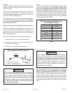
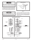
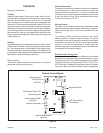
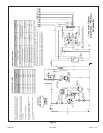
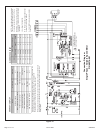
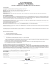
Connection Diagram
Single Phase – Variable Speed Motor
P/N 48374-001
Figure 10
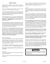
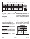
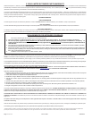
DIAGNOSTIC DISPLAY
Note: Because the pressure switches are monitored only when "Y1" (Input) is active, the
code for pressure switch open will not be seen when "Y1" is off. Instead, the
“Normal Operation" or “Anti-Short Cycle Lockout” code will be seen.
When a pressure switch opens and causes a short cycle lockout, the pressure switch-open
code will be seen until it closes, then the short cycle lockout code will flash unless it has
already expired.
Mode Green LED Red LED
No Power to Board Off Off
Normal Operation/ Power to Board Simultaneous Slow Flash
Anti-Short Cycle Lockout Alternating Slow Flash
Low Pressure Switch Fault Off Slow Flash
Low Pressure Switch Lockout Off On
High Pressure Switch Fault Slow Flash Off
High Pressure Switch Lockout On Off
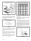
Unit
Factory Shipped Settings
ADJUST HEAT COOL
24 NORM B B
30 NORM A A
36 NORM A A
42 NORM C C
48 NORM B B
60 NORM A A
BLOWER SPEED CHART
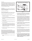
DIAGNOSTIC
MODULE
CONNECTION MUST BE
JUMPERED WHEN PRESSURE
SWITCH IS NOT USED.
2
NOTE - If any of the original wire is replaced,
the same size and type wire must be used.
Use copper conductor only, min. 75°C wire.
WARNING - Electric shock hazard. Unit must
be grounded in accordance with national and
local codes.
Line voltage field installed.
W1 & W2 can be used to stage electric heat
accessory on 15 & 20kW models.
5, 7.5, & 10kW heater accessories function
off W1 only.