


Page 4 of 14 506248-01Issue 0902
Ductwork
Ductwork should be designed and sized according to the
methods in Manual Q of the Air Conditioning Contractors of
America (ACCA).
A closed return duct system shall be used. This shall not
preclude use of economizers or outdoor fresh air intake. It
is recommended that supply and return duct connections at
the unit be made with flexible joints.
The supply and return air duct systems should be designed
for the CFM and static requirements of the job. They should
not be sized by matching the dimensions of the duct
connections on the unit.
Outdoor ductwork must be insulated and waterproofed.
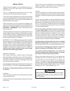
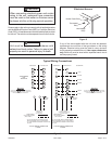
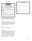
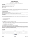
Equipment is shipped for side ductwork connection. The unit
can be converted to bottom ductwork connection by
removing the duct covers located over the bottom duct
openings and placing these covers over the side duct
openings (see Figure 4).
To remove the bottom duct cover over supply opening:
1. Remove screw on cover nearest side opening.
2. Lift end of cover slightly and push to slide back screw/
pin free from duct flange.
3. Slide duct cover out the side duct opening.
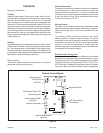
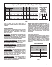
Filters
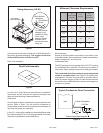
Air filters are to be used with this heating/cooling unit. Filters
are not factory supplied in the unit. However, a filter frame
accessory is available from the manufacturer that allows
filters to be installed within the unit. If the filter frame
accessory is not used, a filter must be installed in the duct
work by the installer. Filters must always be installed ahead
of the evaporator coil and must be kept clean or replaced.
Dirty filters will reduce the airflow of the unit. Filters should be
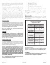
sized in accordance with Table 2.
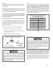
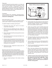
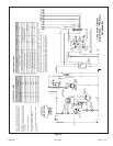
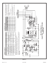
Electrical Wiring
All wiring should be done in accordance with the
National Electrical Code, ANSI/NFPA No. 70 (latest
edition); Canadian Electrical Code Part 1, CSA C22.1
(latest edition); or local codes where they prevail. Use
wiring with a temperature limitation of 75°C minimum. Run
the electric power supply through a fused disconnect switch
to the connection box of the unit and connect as shown in
the wiring diagram located on the inside of the control access
panel.
Figure 4
Removing Bottom Duct Covers
Base
1. Remove screw and lift.
2. Slide cover to free back pin.
1
2
When fastening ductwork to side duct flanges
on unit, insert screws through duct flanges only;
do not insert screws through casing. If using
bottom duct work, do not use screws to secure
ductwork to bottom duct opening under drain
pan side. Using screws to secure bottom duct
may damage drain pan.
CAUTION
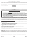
Table 2
Minimum Required Surface Area
for Disposable Filters
gnilooClanimoN
aerAretliF
).tf.qs(
000,4276.2
000,03 33.3
000,6300.4
000,24 76.4
000,8433.5
000,06 76.6
Line voltage is present at all components when
unit is not in operation on units with single pole
contactors. Disconnect all remote electric power
supplies before opening access panel. Unit may
have multiple power supplies. Failure to
disconnect all power supplies could result in
personal injury or death.
WARNING