


506248-01 Page 7 of 14Issue 0902
OPERATION
Sequence of Operation
Cooling
When the thermostat is in the cooling mode, the O circuit is
powered which energizes the reversing valve. Upon cooling
demand, the thermostat closes circuit R and Y. Closing R
and Y closes the unit contactor, starting the compressor and
outdoor fan. The thermostat automatically closes R to G circuit
which also brings on the indoor blower at the same time. Upon
satisfying cooling demand, the thermostat will open the above
circuits and open the main contactor, stopping the compressor
and outdoor fan. If the unit is equipped with a delay timer, the
blower will continue to operate for 90 seconds which improves
system efficiency.
Heating
Upon heating demand, the thermostat closes circuit R to Y, which
closes the unit contactor, starting the compressor and outdoor
fan. The reversing valve is not energized in the heating mode.
The thermostat again automatically brings on the indoor fan at
the same time. Upon satisfying heating demand, the thermostat
opens above circuits and stops unit operation.
Defrost System
The defrost system includes two components: the defrost
thermostat and the defrost control.
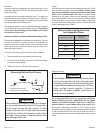
Defrost Thermostat
The defrost thermostat is located on the liquid line between
the check/expansion valve and the distributor. When the
defrost thermostat senses 42°F or cooler, the thermostat
contacts close and send a signal to the defrost control board
to start the defrost timing. It also terminates defrost when
the liquid line warms up to 70°F.
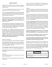
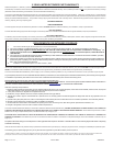
Defrost Control
The defrost control board includes the combined functions
of time/temperature defrost control, defrost relay, diagnostic
LEDs and terminal strip for field wiring connections (see
Figure 8).
The control provides automatic switching from normal
heating operation to defrost mode and back. During the
compressor cycle (call for defrost), the control accumulates
compressor run time at 30, 60, 90 minute field-adjustable
intervals. If the defrost thermostat is closed when the
selected compressor run time interval ends, the defrost relay
is energized and the defrost begins.
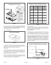
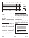
Defrost Control Timing Pins
Each timing pin selection provides a different accumulated
compressor run time period during one thermostat run cycle.
This time period must occur before a defrost cycle is initiated.
The defrost interval can be adjusted to 30 (T1), 60 (T2), or
90 (T3) minutes. The defrost timing jumper is factory installed
to provide a 60-minute defrost interval. If the timing selector
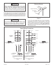
Defrost Control Board
Figure 8
Defrost Interval
Timing Pins
Diagnostic LEDs
24V TerminalStrip
Connections
High Pressure Switch
(optional)
Defrost Thermostat
Reversing Valve
Compressor Delay Pins
Test Pins
K1 Relay
K2 Relay
FAN
DS1
L
24V
P2
P5
O-OUT
DF
Y1-OUT
HI-PS
U1
U2
DS2
K3 Relay
P6
TST PS DF C R O Y1
C5
LO-PS
C2
P1
30
60
90
TEST
W1
C
L
R
Y1
O
Low Pressure Switch
(optional)