


506248-01 Page 3 of 14Issue 0902
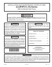
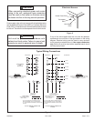
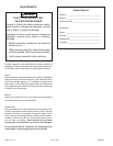
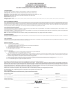
Using Accessory Lift Kit
Figure 1
Units may also be moved or lifted with a forklift while still in
the factory-supplied packaging. The lengths of the forks
of the forklift must be a minimum of 42".
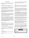
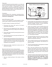
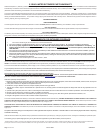
Roof Curb Installation
If a roof curb is used, follow the manufacturer’s Installation
Instructions and be sure that all required clearances are
observed (see following Clearances section).
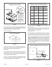
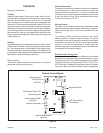
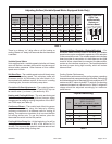
Clearances
All units require certain clearances for proper operation and
service. Refer to Table 1 for the minimum clearances to
combustibles as well as minimum clearances necessary for
servicing and proper unit operation.
In the U.S., units may be installed on combustible floors made
from wood or class A, B, or C roof covering material. In Canada,
units may be installed on combustible floors.
Service Access
Access to all serviceable components is provided by four
removable panels: filter compartment, blower compartment,
heater compartment, and top panel.
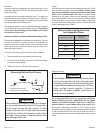
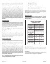
Condensate Drain
The PHP package unit is equipped with a 3/4" FPT coupling
for condensate line connection. Plumbing must conform to
local codes. Use a sealing compound on male pipe threads.
The condensate drain line must be properly trapped and
routed to a suitable drain. See Figure 3 for proper drain
arrangement. The drain line must pitch to an open drain or
pump to prevent clogging of the line. Seal around the drain
connection with suitable material to prevent air leakage into
the return air system.
To avoid possible
damage to unit
panels from lifting
clevis, place
packing material
between clevis
and panels before
lifting unit.
Spreaders
(Field Supplied)
Lifting Bracket
Accessory
Sheet Metal
Screw
Roof Curb Assembly
Figure 2
Table 1
oT
elbitsubmoC
lairetaM
roF
ecivreS
roF
reporP
noitarepO
tnorF"0"84"3
raeR "0 "42 "3
resnednoC
dnE
"0"42"3
rewolB
dnE
"0 "03 "0
poT"0"63"63
Minimum Clearance Requirements
Unit
Drain Connection
Positive Liquid Seal Required
3.00" Min.
1.00" Min.
12.00"
Max.
Typical Condensate Drain Connection
Figure 3